E5 Series High Performance Universal Inverter User’s Manual
100
Chapter 6 Parameter Descriptions
If current limit function is enabled, when the current exceeds current limit level (PA.05), the inverter will
turn into current limit status. If the current level drops below current limit value (PA.05), exit the current
limit status automatically, then normal operation will continue.
Note:
Current limit level PA.05=T60.0% indicates T.6 times of rated current of inverter.
Under current limit status, the speed will be decreased. The current limit function is not appropriate for
systems that can not reduce speed, otherwise will loss control.
The setting range is from T0.0% to T50.0% and the default value is TT0.0% for E5−A series.
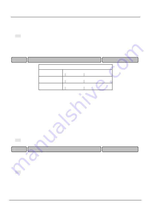
PA.06 Auto voltage regulation
Ones place
Over voltage regulation
0: Disabled T: Enabled
Tens place
Under voltage regulation
0: Disabled T: Enabled
Hundreds place
Over-modulation
0: Disabled T: Enabled
DC bus voltage will rise when motor with large inertial load stops rapidly, or a short time regenerative
braking happens for load abrupt changes when the motor is running, thus may cause over voltage
protection. Over voltage regulation is used to decrease the braking torque to control the DC bus voltage
to prevent over voltage fault through adjusts output frequency and auto prolongs deceleration time.
When power supply voltage decreases or has instantaneous power failure, DC bus voltage will also
decrease. The function of under voltage regulation is use to decrease the motor speed through
decreasing the output frequency, the load inertial energy feedback to DC bus to keep DC voltage higher
than the under voltage value, avoid stop by under voltage. Under voltage regulation is very effective in
applications such as centrifugal pump and fan.
Over-modulation is used to increase the output voltage and enhance the output capacity under low grid
voltage input or heavy load.
Note:
If dynamic braking is enabled and PA.09 has been set to “T”, over voltage regulation function is disabled.
This parameter is used to decrease the output voltage automatically when the loads decrease under
proper operation to maximally decreases reactive power to offer more energy savings. The greater the
parameter setting, the more visible the energy saving effect achieves, but the longer the response time
lasts from energy saving condition to normal operation status.
Note:
This function is inactive during acceleration and deceleration process.
The function applies to variable torque loads such as fan and pump. If used in constant torque loads
and rapidly changing loads applications, the function will result in delayed control response.
0 ~ 50 %( 0%)
Energy-saving rate
PA.07
000 ~ TTT(T0T)
Auto voltage regulation
PA.06
Summary of Contents for E5 Series
Page 1: ...E5 Series High Performance Universal Inverter USER S MANUAL E5 Series USER S MANUAL ...
Page 7: ...vi T Setting Process for Open Loop ...
Page 8: ...vii Open loop setting process continued ...
Page 9: ...viii 3 Setting Process for Closed Loop ...
Page 10: ...ix Setting Process for Closed Loop continued ...


