


Configuring 802.1Q VLAN
Configuration Example
Configuration Guide
187
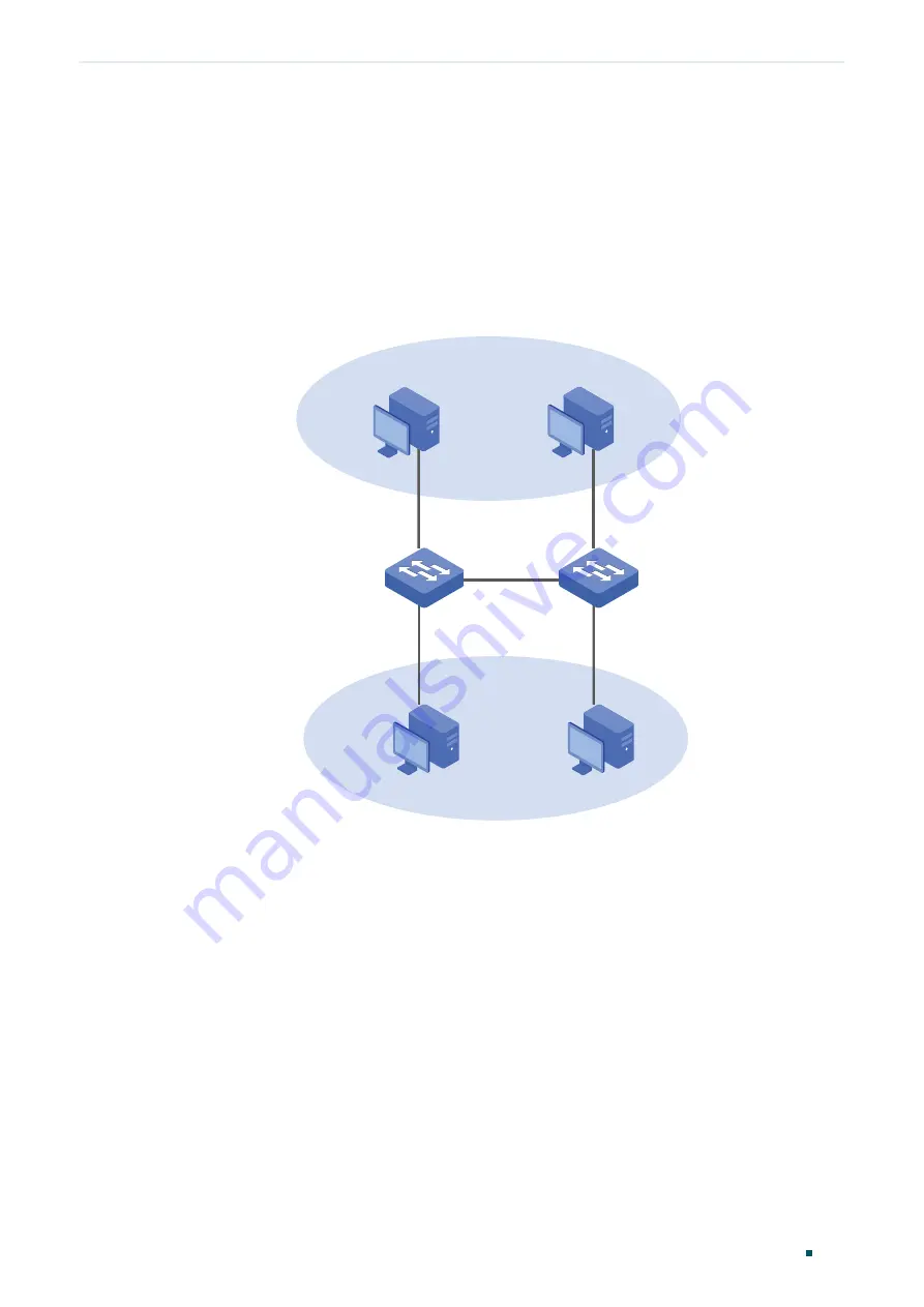
3.3 Network Topology
The figure below shows the network topology. Host A1 and Host A2 are used in
Department A, while Host B1 and Host B2 are used in Department B. Switch 1 and Switch
2 are located in two different places. Host A1 and Host B1 are connected to port 1/0/2 and
port 1/0/3 on Switch 1 respectively, while Host A2 and Host B2 are connected to port 1/0/6
and port 1/0/7 on Switch 2 respectively. Port 1/0/4 on Switch 1 is connected to port 1/0/8
on Switch 2.
Figure 3-1
Network Topology
VLAN 10
VLAN 20
Host A1
Host A2
Host B1
Host B2
Switch 1
Switch 2
Gi1/0/2
Gi1/0/3
Gi1/0/4
Gi1/0/6
Gi1/0/7
Gi1/0/8
The following sections provide configuration procedure in two ways: using the GUI and
using the CLI.
3.4 Using the GUI
The configurations of Switch 1 and Switch 2 are similar. The following introductions take
Switch 1 as an example.
1) Choose the menu
VLAN > 802.1Q VLAN > Port Config
to load the following page. For
port 1/0/2 and port 1/0/3, set the link type as
Access
; for port 1/0/4, set the link type as
Trunk
. Then click
Apply
.
Summary of Contents for T2500G-10MPS
Page 1: ...User Guide T2500G 10MPS 1910012405 REV1 0 1 April 2018...
Page 24: ...Using the CLI 767 Appendix Default Parameters 773...
Page 145: ...Part 5 Monitoring Traffic CHAPTERS 1 Traffic Monitor 2 Appendix Default Parameters...
Page 172: ...Part 7 Configuring DDM CHAPTERS 1 Overview 2 DDM Configuration 3 Appendix Default Parameters...


