


Description of Functions
9-23
FM 353 Stepper Drive Positioning Module
6ES7 353-1AH01-8BG0
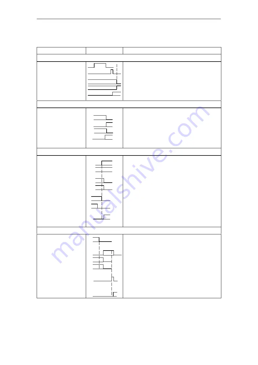
Control actions for “Reference point approach” mode (examples), continued
Signal name
Explanation
Level
Control action 3, reference point switch (RPS) reached
RPS
Encoder zero marker
Checkback signals:
Travel plus [FR+]
Travel minus [FR
−
]
Synchronized [SYN]
When the RPS is reached, the velocity is reduced. The
encoder is synchronized when the zero marker is de-
tected. The axis is positioned by traversing through the
reference point offset to the reference point (the direc-
tion is reversed if necessary).
Control action 4, approach reference point
Checkback signals:
Travel minus [FR
−
]
Position reached, stop
[PEH]
Processing in progress
[BL]
Start enable [SFG]
When reference point is reached.
[FR
−
] is removed.
[PEH] is set.
[BL] is also removed.
[SFG] is set.
Control action 5, ambiguous direction command (special situation)
Control signals:
Direction plus [R+]
Direction minus [R
−
]
Checkback signals:
Travel minus [FR
−
]
Processing in progress
[BL]
Control signals:
Direction plus [R+]
Direction minus [R
−
]
Checkback signal:
Start enable [SFG]
[R+] is defined although [R
−
] is active.
The ambiguous direction command causes the axis to
stop. [FR
−
] and [BL] are canceled, and an error is out-
put.
The [SFG] does not reappear until [R+] and [R
−
] have
been canceled].
Control action 6, cancel servo enable (special situation)
Single function ”Servo En-
able” (DBX34.0)
Checkback signals:
Oper./travel error [BF/FS]
Travel minus [FR
−
]
Processing in progr. [BL]
Control signal:
Acknowledge operator/
travel error [BFQ/FSQ]
Checkback signals:
Start enable [SFG]
The “servo enable” is deactivated during the traversing
movement.
The axis is stopped immediately and outputs an error.
[FR
−
] and [BL] are canceled.
When the error is acknowledged, the error message is
canceled and the start enable is activated.
Summary of Contents for SIMATIC FM 353
Page 22: ...Product Overview 1 12 FM 353 Stepper Drive Positioning Module 6ES7 353 1AH01 8BG0 ...
Page 32: ...Installing and Removing 3 6 FM 353 Stepper Drive Positioning Module 6ES7 353 1AH01 8BG0 ...
Page 282: ...Description of Functions 9 82 FM 353 Stepper Drive Positioning Module 6ES7 353 1AH01 8BG0 ...
Page 354: ...User Data Block AW DB B 16 FM 353 Stepper Drive Positioning Module 6ES7 353 1AH01 8BG0 ...


