8017035/ZMO9/2017-06-08 • © SICK AG • Subject to change without notice.
23
Operating the Sensor
5 Operating the Sensor
5.1
Sensor Screen
5.1.1
Details of the Screen
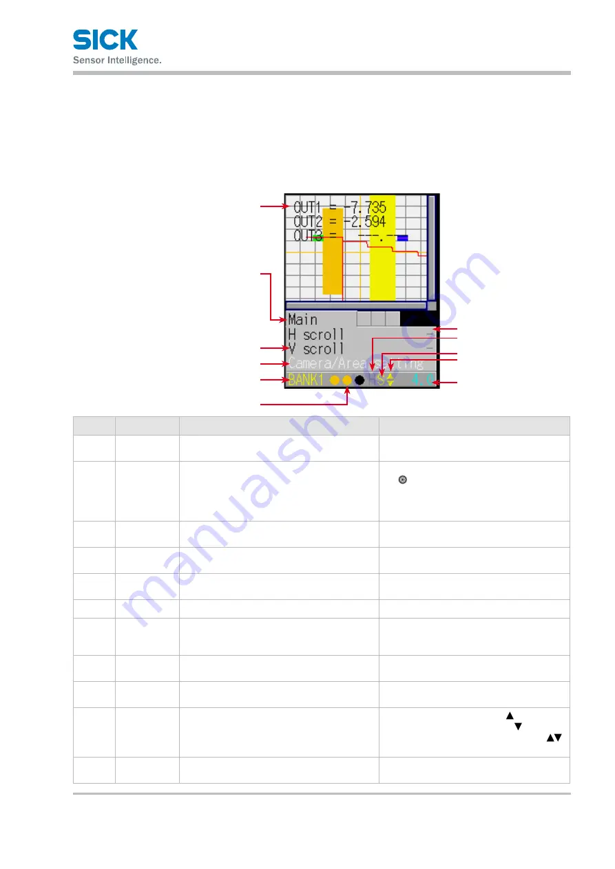
This section explains the details of the screen display.
1
2
3
4
5
6
7
8
ß
9
à
Number Display item
Description
Operation
1
Main screen
The camera screen, profile waveform, and set
area are displayed here.
—
2
Tab
The menu categories are displayed here.
You can also select this part.
Move the cursor to the tab, and then press
the “SET” button to switch between the
tabs in order.
When not selected: Black
When selected: Blue
3
Setting menu
The setting menu is displayed here.
Three settings are displayed at one time.
—
4
Setting menu
(selected)
When a setting is selected, the color changes.
When selected: White
When setting the para meter: Yellow
5
Parameter
The parameters for the settings are displayed
here.
When item selected: White
When setting the para meter: Yellow
6
Bank number The current bank number is displayed here.
—
7
Output
The control output statuses are displayed here
in the order – from the left – control output 1,
control output 2, control output 3.
When output is off: Black
When output is on: Orange
8
Hold input
When the input is being held, an “H” is
displayed here.
When input is being held:
“H” displayed in yellow
9
Storage func-
tion
The storage function operation status is dis-
played here.
Trigger standby: Green
Storing: Yellow
ß
Cursor/Key
Lock
A cursor that indicates the direction that
the screen can move in is displayed here or a "L"
that indicates the activated key lock.
When the screen can move up:
When the screen can move down:
When the screen can move up and down:
When the keys are locked: L
à
Sampling
period
The sampling period is displayed here.
The unit is “ms.”
—


