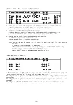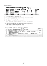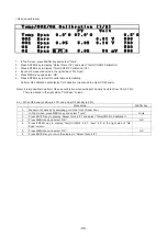
- 24 -
㻌
㻌
㻌
㻌 㻌 㻌
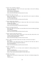
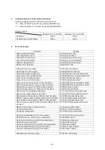
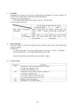
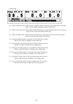
<Alarm display>
㻌
䣖 䣧 䣯 䣲
䢵 䢹 䢰 䢲 䤑䣅
䣅 䣑 䢴
䢷 䢰 䢲 䢧
䣑 䢴
䢷 䢰 䢲 䢧
䣃
䣄
䣕 䣶 䣣 䣶 䣷 䣵
䣙 䣣 䣴 䣰 䣫 䣰 䣩 䢼 䣊 䣫 䣩 䣪
䣖 䣧 䣯 䣲
䢷 䢰 䢲
䢷 䢰 䢲
䢵 䢺 䢰 䢷
㻌
㻌
z
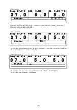
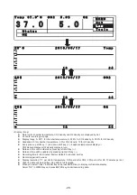
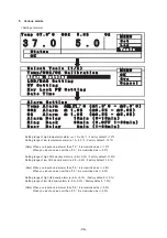
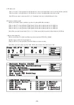
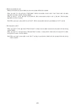
High/low temperature alarm: When high/low temperature alarm is occurred and alarm delay time is not expired,
digits of current chamber temperature display starts blinking.
z
High/low CO2 density alarm: When high/low CO2 density alarm is occurred and alarm delay time is not expired,
digits of current CO2 density display starts blinking.
z
Hihg/low O2 density alarm: When high/low O2 density alarm is occurred and alarm delay time is not expired,
digits of current O2 density display starts blinking.
z
When high temperature alarm is occurred and alarm delay time is expired;
“Warning : High Temp” is displayed in the message field
z
When low temperature alarm is occurred and alarm delay time is expired;
“Warning : Low Temp” is displayed in the message field.
z
When high CO2 density alarm is occurred and alarm delay time is expired;
“Warning : High CO2 Density “ is displayed in the message field.
z
When low CO2 density alarm is occurred and alarm delay time is expired;
“Warning: Low CO2 Density” is displayed in the message field.
z
When high O2 density alarm is occurred and alarm delay time is expired;
“Warning: High O2 Density” is displayed in the message field.
z
When low O2 density alarm is occurred and alarm delay time is expired;
“Warning: Low O2 Density” is displayed in the message field.
Summary of Contents for MCO-19M
Page 7: ... 4 Dimensions Power cord ...
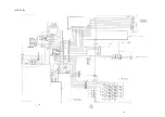
Page 16: ...Wiring diagram 13 ...
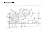
Page 17: ...Circuit diagram Main PCB 14 ...
Page 18: ... LCD PCB 15 ...
Page 110: ...MCO 19M UVH MCO 19M UV MCO 19M Multi Gas Incubator INSTRUCTION MANUAL 107 ...
Page 112: ...CONTENTS SPECIFICATIONS P 74 PERFORMANCE P 75 SAFETY CHECK SHEET P 76 109 2 ...
Page 183: ...Fig A Stacking plate B Stacking plate A Protective sticker Front panel Hook Front 180 73 ...
Page 187: ...SANYO Electric Co Ltd Printed in Japan DC3186 150B ...

