- 97 -
Operation check after installation of MCO-21GC
(for MCO--20AIC/MCO-18AIC/MCO-18M/MCO-18AC)
After the installation of MCO-21GC is complete, check the operation according to the following procedures.
Procedures
1
Stop the gas supply from cylinder A and use only cylinder B.
2
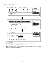
Turn on the power switch of MCO-20AIC/18AIC/18AC and set 37 and 0%.
Check if the gas cylinder A is selected.
For MCO-20AIC/MCO-18AIC/18AC, check if CO
2
gas supply line indicator A lights.
For MCO-18M, check if the CO
2
gas supply line indicator lights.
3
Leave it for approx. 1 hour until the apparatus can control the CO
2
density.
(It may take approx. 1 hour to enable the apparatus to control CO
2
after the power is turned on.)
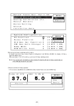
4 Set
CO
2
in 5% and check if the CO
2
inject lamp turns on.
NOTE: In case of low ambient temperature, it may take more than 1 hour until the apparatus can
control CO
2
density and the CO
2
inject lamp lights.
5
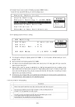
Check if E01(CO
2
gas cylinder becomes empty) is displayed and buzzer sounds after 2-7minutes
later since the CO
2
inject lamp lights.
Check if the cylinder A is switched to the cylinder B.
For MCO-20AIC/MCO-18AIC/18AC, check if CO
2
gas supply line indicator A starts blinking and
the indicator B lights.
For MCO-18M, check if the CO2 gas supply line indicator starts blinking.
6
Check if the CO
2
density is displayed as 5% and keep it stabilized.
NOTE: When the decimal point blinks on the CO
2
display during CO
2
sensor calibration, CO
2
control may be interrupted.
7
After operation check is complete, shut down the CO
2
supply of cylinder A and cylinder B.
Press BUZZER key to eliminate the "E01" message.
Select the gas cylinder A.
For MCO-20AIC/MCO-18AIC/18AC, select the cylinder A by pressing CO
2
gas supply line
switching key.
For MCO-18M, press CO
2
gas supply line switching key during CO
2
density setting mode to
light CO
2
injection lamp.
Refer to the MCO-20AIC/18AIC/18M instruction manual for the usage of MCO-21GC
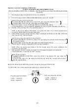
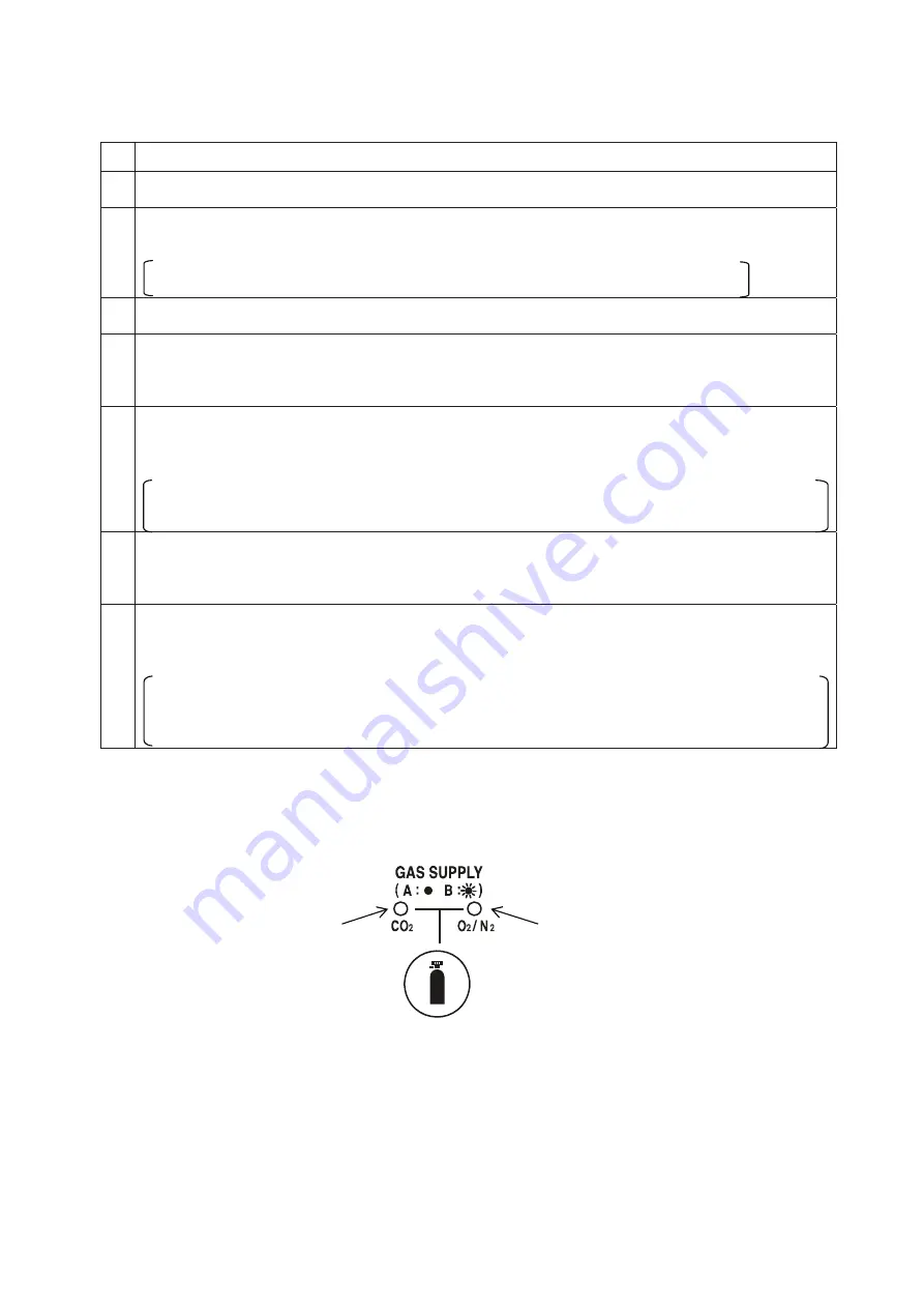
* For MCO-18M, the currently selected gas supply line is indicated as follow:
N
2
/O
2
gas supply line indicator
CO
2
gas supply line indicator
Lights
Ჴ
Cylinder A
Blinks
Ჴ
Cylinder B
Lights
Ჴ
Cylinder A
Blinks
Ჴ
Cylinder B
Summary of Contents for MCO-19M
Page 7: ... 4 Dimensions Power cord ...
Page 16: ...Wiring diagram 13 ...
Page 17: ...Circuit diagram Main PCB 14 ...
Page 18: ... LCD PCB 15 ...
Page 110: ...MCO 19M UVH MCO 19M UV MCO 19M Multi Gas Incubator INSTRUCTION MANUAL 107 ...
Page 112: ...CONTENTS SPECIFICATIONS P 74 PERFORMANCE P 75 SAFETY CHECK SHEET P 76 109 2 ...
Page 183: ...Fig A Stacking plate B Stacking plate A Protective sticker Front panel Hook Front 180 73 ...
Page 187: ...SANYO Electric Co Ltd Printed in Japan DC3186 150B ...


