


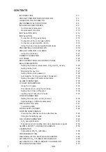

CONTENTS
INTRODUCTION
P.
3
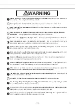
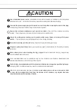
PRECAUTIONS FOR SAFE OPERATION
P.
4
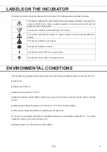
LABELS ON THE INCUBATOR
P. 8
ENVIRONMENTAL
CONDITIONS P.
8
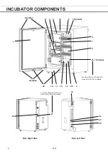
INCUBATOR
COMPONENTS
P.
9
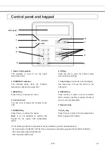
Control panel and keypad
P. 12
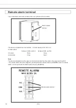
Remote
alarm
terminals
P.
13
INSTALLATION
SITE
P.
14
INSTALLATION
P.
15
Connection of CO
2
gas
cylinder P.
16
Connection of N
2
(or O
2
) gas cylinder
P. 17
Connection of gas injection nozzle
P. 18
Using the inner door and gastight split doors
P. 18
PREVENTING
CONTAMINATION P.
19
PRECAUTIONS
FOR
CULTURES
P.
20
Using the unlock key
P. 21
CORRECT
OPERATION
P.
21
LCD
PANEL
P.
22
BASIC OPERATIONS ON CONTROL PANEL
P. 24
BASIC
PARAMETERS
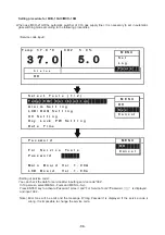
Setting the chamber temperature, CO
2
and CO
2
density
P. 25
Setting the key lock
P. 26
Releasing the key lock
P. 27
Setting the key lock password
P. 28
Automatic N
2
(or O
2
) gas cylinder changeover
P. 30
Setting the upper limit alarm temperature
P. 32
ALARM PARAMETERS
P. 33
UV
LAMP
PARAMETERS
P.
34
Using
the
UV
lamp
P.
34
Precautions when using the UV lamp
P.
35
Setting the UV lamp ON period
P. 36
Lighting the UV lamp for 24 hours
P. 37
OTHER
PARAMETERS
Setting the date, time, and log interval
P. 38
Initial settings (LCD/DAQ parameters)
P. 40
DISPLAYING
THE
LOG P.
41
Transferring data
P. 43
WATER
LEVEL
SENSOR
P.
44
ROUTINE MAINTENANCE
Cleaning the chamber and inner attachments
P. 45
Filling the humidifying pan
P. 48
H
2
O
2
DECONTAMINATION
P.
49
H
2
O
2
decontamination P.
51
Precautions when handling H
2
O
2
decontamination reagent
P. 54
ALARMS, SAFETY, AND SELF-DIAGNOSIS
P. 55
CALIBRATION
Temperature/CO
2
/O
2
calibration P.
58
TROUBLESHOOTING
P.
60
DISPOSING OF THE MULTI-GAS INCUBATOR
P. 62
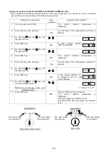
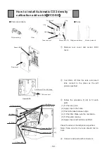
AUTOMATIC CO
2
CYLINDER CHANGEOVER
P. 67
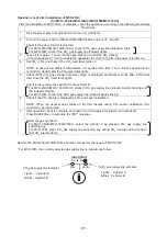
AUTOMATIC CO
2
AND O
2
DENSITY CALIBRATION
P. 69
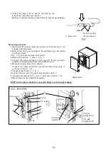
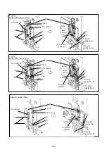
STACKING
INCUBATORS
P.
72
- 108 -
1
Summary of Contents for MCO-19M
Page 7: ... 4 Dimensions Power cord ...
Page 16: ...Wiring diagram 13 ...
Page 17: ...Circuit diagram Main PCB 14 ...
Page 18: ... LCD PCB 15 ...
Page 110: ...MCO 19M UVH MCO 19M UV MCO 19M Multi Gas Incubator INSTRUCTION MANUAL 107 ...
Page 112: ...CONTENTS SPECIFICATIONS P 74 PERFORMANCE P 75 SAFETY CHECK SHEET P 76 109 2 ...
Page 183: ...Fig A Stacking plate B Stacking plate A Protective sticker Front panel Hook Front 180 73 ...
Page 187: ...SANYO Electric Co Ltd Printed in Japan DC3186 150B ...


