


- 81 -
䐠䠱䠲
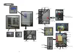
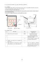
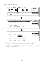
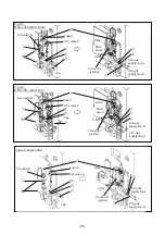
lamp cover
䐟䠱䠲
lamp
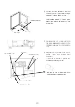
Fig. 4
䐡
Screw
㻌
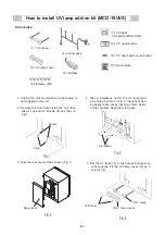
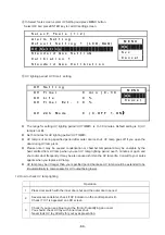
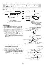
How to install UV lamp add-on kit (MCO-19UVS)
㻌
㻌
1. Unplug the unit and make sure that power is
not supplied to the unit.
2. Remote the duct from inside the unit, then
take 2 caps and 2 screws off as shown in
Fig.1
㻌
㻌
㻌
㻌
㻌
㻌
㻌
㻌
㻌
㻌
㻌
㻌
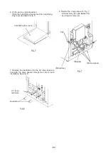
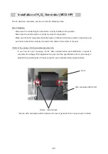
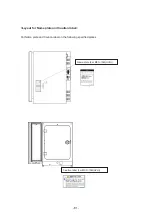
3. Take the rear cover off as shown in Fig. 2.
㻌
㻌
㻌
㻌
㻌
㻌
㻌
㻌
㻌
㻌
㻌
㻌
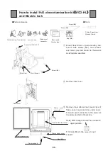
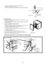
Insulation
Fig. 3
Rear cover
Fig. 2
4. Take 2 insulations out for the UV lamp lead
wire hole as shown in Fig. 3. Insulations can
be easily taken out by pushing it from inside
of the chamber. Keep them for reuse.
5. Set the UV lamp (
䐟
) to the hole and make sure
to fit correctly. Fix the UV lamp cover (
䐠
) by 2
screws (
䐡
).
Screw
Fig. 1
Cap
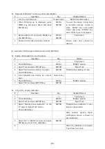
䐟
1 UV lamp
䐠
1 UV lamp cover
䐡
6 Screws
䠄
M4
䠅
䐣
1 Ballast
䐥
1 UV label
(Unused for MCO-19M)
䐢㻌
2 Glow ass’y
䐦
1 UV caution label
䐧
1 UV door switch caution label
䐨
5 Name plate
Kit includes:
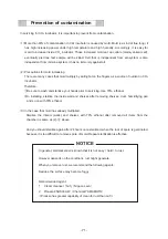
Summary of Contents for MCO-19M
Page 7: ... 4 Dimensions Power cord ...
Page 16: ...Wiring diagram 13 ...
Page 17: ...Circuit diagram Main PCB 14 ...
Page 18: ... LCD PCB 15 ...
Page 110: ...MCO 19M UVH MCO 19M UV MCO 19M Multi Gas Incubator INSTRUCTION MANUAL 107 ...
Page 112: ...CONTENTS SPECIFICATIONS P 74 PERFORMANCE P 75 SAFETY CHECK SHEET P 76 109 2 ...
Page 183: ...Fig A Stacking plate B Stacking plate A Protective sticker Front panel Hook Front 180 73 ...
Page 187: ...SANYO Electric Co Ltd Printed in Japan DC3186 150B ...


