䛆
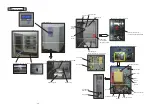
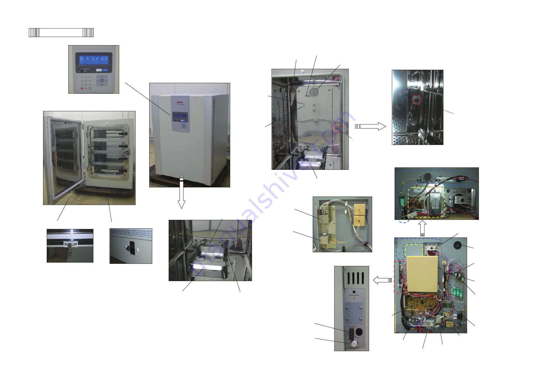
LCD control panel
䛇
CO2 inject pipe
Access hole
Circulating fan
䛆
Inner wall
䛇
䛆
MCO-HL is optionally installed
䛇
䛆
MCO-19M(UV)
䛇
Overheat
protect
sensor
䛆
Outer door is open
䠄
inner door is closed
䠅䛇
Silicone cap attached
during H2O2 decontamination
Temp.
sensor
Silicone cap
is not attached
(Covered by plate)
䛆
H2O2 generator
䠄
MCO-HL)
䠄
MCO-SG)
䛇䞉䞉䞉
Option
Humidifying pan
䛆
Sensor BOX
䠄
Cover is removed
䠅䛇
CO2 sensor
䛆
Inner bottom
䛇
UV lamp
䠄
Option for MCO-19M
䠅
䛆
Electric lock on door (Option)
䛇
䛆
Electric lock on unit (Option
䠅䛇
O2 sensor
Circulating fan motor
䛆
Back side
䛇
Access hole
CO2 valve
O2/N2
valve A
Humidifying pan
Water sensor
O2/N2
valve B
Remote alarm
Main PCB
terminal
PCB for O2 sensor
Glow starter
Noise filter
Switching power supply
Power transformer
Ballast
Parts layout
- 76 -
Summary of Contents for MCO-19M
Page 7: ... 4 Dimensions Power cord ...
Page 16: ...Wiring diagram 13 ...
Page 17: ...Circuit diagram Main PCB 14 ...
Page 18: ... LCD PCB 15 ...
Page 110: ...MCO 19M UVH MCO 19M UV MCO 19M Multi Gas Incubator INSTRUCTION MANUAL 107 ...
Page 112: ...CONTENTS SPECIFICATIONS P 74 PERFORMANCE P 75 SAFETY CHECK SHEET P 76 109 2 ...
Page 183: ...Fig A Stacking plate B Stacking plate A Protective sticker Front panel Hook Front 180 73 ...
Page 187: ...SANYO Electric Co Ltd Printed in Japan DC3186 150B ...

