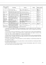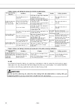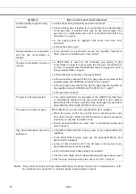
Alarm or safety
function
Conditions Display
Buzzer
Safety
operation
O
2
sensor error
The measured voltage
for the O
2
sensor is abnormal.
Err19: O
2
Sensor Abnormal
is
displayed in the message display field.
Intermittent tone
N
2
/O
2
valve is
closed.
Remote alarm
operates
Main heater
error
Main heater burnout occurs or the main
heater SSR is short-circuited when the
upper limit temperature alarm operates.
Err13: Main Heater Abnormal
is
displayed in the message display field.
〃
Remote alarm
operates.
Bottom heater
error
Bottom heater burnout occurs or the
bottom heater SSR is short-circuited.
Err14: Humidity Heater Abnormal
is displayed in the message display
field.
〃
Remote alarm
operates.
Door heater
error
Door heater burnout occurs or the door
heater SSR is short-circuited.
Err15: Door Heater Abnormal
is
displayed in the message display field.
〃
Remote alarm
operates.
Sensor box
heater error
Sensor box heater burnout occurs
or the sensor box heater SSR is
short-circuited.
Err16: CO
2
S Box Heater Abnormal
is
displayed in the message display field.
〃
Remote alarm
operates.
Heater SSR
burnout
Main, bottom, door, or sensor box
heater SSR burnout occurs.
Err17: Heater SSR Open
is displayed
in the message display field.
〃
Remote alarm
operates.
Low humidifying
water
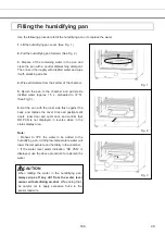
The water in the humidifying pan
drops to approx. 600 ml.
RH PAN
flashes in reverse video in the
status display field.
----- -----
UV lamp failure
The UV lamp burns out (only for the
MCO-19M(UVH)/19M(UV) or when the
optional MCO-19UVS is installed).
Err18: UV Lamp Abnormal
is displayed
in the message display field.
Intermittent tone
Remote alarm
operates.
New UV lamp
recommended
The accumulated ON time reaches
approx. 1,000 hours (only for the
MCO-19M(UVH)/19M(UV) or when the
optional MCO-19UVS is installed).
Warning :UV Life
is displayed in the
message display field.
----- -----
The buzzer can be stopped by pressing the BUZZER Key, but remote alarms will not stop. In addition, a
buzzer that sounds because of the upper limit temperature alarm cannot be stopped by pressing the
BUZZER Key.
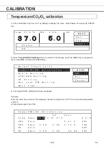
Err01 recovery is achieved automatically by correctly connecting the gas and pressing the BUZZER Key
to stop the buzzer. In addition, when the MCO-21GC is installed and the gas supply is switched to the
reserve gas cylinder, press the BUZZER Key and replace the gas cylinder.
Err02 recovery is achieved automatically by correctly connecting the gas and pressing the BUZZER Key
to stop the buzzer. In addition, when the gas supply is switched to the reserve gas cylinder, press the
BUZZER Key and replace the gas cylinder.
For Err03, confirm whether a CO2 gas cylinder is correctly connected to a connecting port A/B for CO
2
gas pipe. Refer to page 16
For Err04, confirm whether a N
2
(or O
2
) gas cylinder is correctly connected to a connecting port A/B for
N
2
/O
2
gas pipe. Refer to page 17
If an error from Err05 to Err19 occurs (except for the upper limit temperature alarm in Err13 to Err16),
then consult a Sanyo sales representative or agent.
- 163 -
56
Summary of Contents for MCO-19M
Page 7: ... 4 Dimensions Power cord ...
Page 16: ...Wiring diagram 13 ...
Page 17: ...Circuit diagram Main PCB 14 ...
Page 18: ... LCD PCB 15 ...
Page 110: ...MCO 19M UVH MCO 19M UV MCO 19M Multi Gas Incubator INSTRUCTION MANUAL 107 ...
Page 112: ...CONTENTS SPECIFICATIONS P 74 PERFORMANCE P 75 SAFETY CHECK SHEET P 76 109 2 ...
Page 183: ...Fig A Stacking plate B Stacking plate A Protective sticker Front panel Hook Front 180 73 ...
Page 187: ...SANYO Electric Co Ltd Printed in Japan DC3186 150B ...


