- 94 -
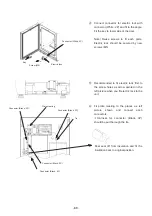
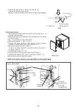
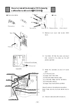
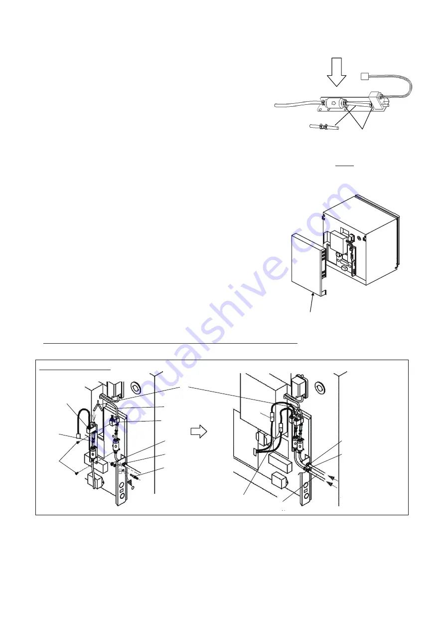
3. Attach the tube L100
ĵ
and fix the tube by the
tube bands removed in procedure 1.
Make sure the tube bands are fixed firmly to prevent gas leakage.
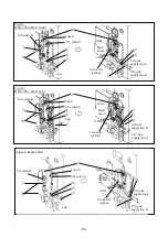
Mounting procedure
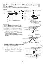
1.Disconnect the power cable and make sure that the unit is not
supplied with the power.
2.Remove the rear cover specified in the right figure by unscrewing
the fixing screws.
3.Fix
ձ
by using the enclosed screws(
ո
).
4.Remove cap and fix
յ
with
ճ
and
մ
.
5.Connect the wiring harness of CO
2
valve B to the connector
(yellow) of wiring harness from CN9 on Main board.
6.Disconnect upper tube of CO
2
valve A.
Connect CO
2
valve A and CO
2
valve B and tube X by using
ղ
as shown in Fig.3-1
㹼
3-4.
7.Connect bottom tube of
ձ
to
ճ
.
8.Connect the port with CO
2
gas supply line B by using
չ
.
9 .Fix tubes securely using
ն
and
շ
as shown in Fig.3-1
㹼
3-4.
10.Mount the rear cover back to the place
NOTE: All the tubes should be connected firmly to prevent gas leakage.
Rear cover
CO
2
valve B
Tube X
Connector
(yellow)
white
Main
board
cap
CN9
CO
2
gas
supply line B
Fig.3-1
MCO-20AIC
CO
2
gas
supply line A
CO
2
valve A
ĭ
Ĭ
ij
į
İ
Į
Ĵ
IJ
ı
Fig.2
ĵ
tube L100
Fix both ends by
the tube bands
Summary of Contents for MCO-19M
Page 7: ... 4 Dimensions Power cord ...
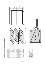
Page 16: ...Wiring diagram 13 ...
Page 17: ...Circuit diagram Main PCB 14 ...
Page 18: ... LCD PCB 15 ...
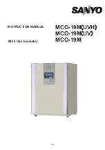
Page 110: ...MCO 19M UVH MCO 19M UV MCO 19M Multi Gas Incubator INSTRUCTION MANUAL 107 ...
Page 112: ...CONTENTS SPECIFICATIONS P 74 PERFORMANCE P 75 SAFETY CHECK SHEET P 76 109 2 ...
Page 183: ...Fig A Stacking plate B Stacking plate A Protective sticker Front panel Hook Front 180 73 ...
Page 187: ...SANYO Electric Co Ltd Printed in Japan DC3186 150B ...

