- 96 -
F 0 3 0 0 0
F 0 8 0 * *
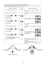
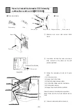
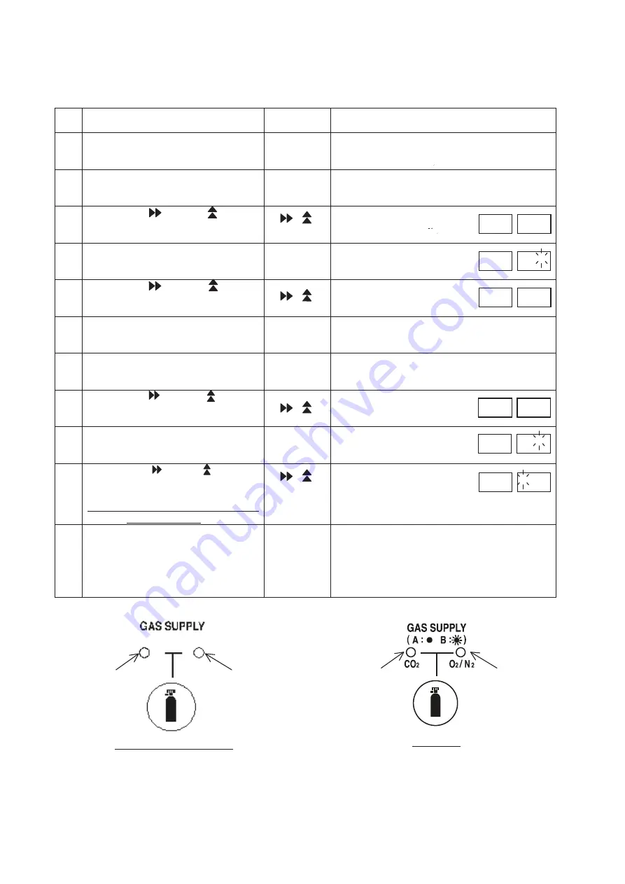
Setting procedures for MCO-20AIC/MCO-18AIC/MCO-18M/MCO-18AC
When use MCO-21GC(the automatic switcher of CO
2
gas supply line), it is necessary to set in automatic
gas switching mode according to the following procedures.
Description of operation
Key
operated
Indication after operation
1
Turn the power switch ON.
-
The current chamber temperature is
displayed.
2
Press CAL key for 5 seconds.
CAL
The left digit in the temperature indicator is
flashed.
3 By pressing key and key, set
the figure to F03.
4 Press
ENT
key.
ENT
In CO
2
density indicator,
"000" is displayed.
5 By pressing key and key, set
the figure to 384
6 Press
ENT
key.
ENT
The current chamber temperature is
displayed.
7
Press CAL key for 5 seconds.
CAL
The left digit in the temperature indicator is
flashed.
8 By pressing key and key, set
the figure to F08
9 Press
ENT
key.
ENT
In CO
2
density indicator, "0**"
is displayed and the right
digit is flashed.
10 By pressing key and key, set
only the left digit figure to 1.
NOTE: Do not change center and
right digit figure.
"
㸨
" means "0" or "1".
11 Press
ENT
key.
ENT
Setting of MCO-21GC is finished.
The current chamber temperature is
displayed.
CO
2
gas supply line indicator A is lit.
(For MCO-18M, CO
2
gas supply line indicator
is lit.)
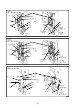
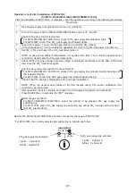
F 0 3
F 0 3 3 8 4
F 0 8
F 0 8 1 * *
N
2
/O
2
gas supply
line indicator
CO
2
gas supply
line indicator
MCO-18M
CO
2
gas supply
line indicator A
MCO-20AIC/18AIC/18AC
$
%
CO
2
gas supply
line indicator B
Summary of Contents for MCO-19M
Page 7: ... 4 Dimensions Power cord ...
Page 16: ...Wiring diagram 13 ...
Page 17: ...Circuit diagram Main PCB 14 ...
Page 18: ... LCD PCB 15 ...
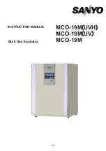
Page 110: ...MCO 19M UVH MCO 19M UV MCO 19M Multi Gas Incubator INSTRUCTION MANUAL 107 ...
Page 112: ...CONTENTS SPECIFICATIONS P 74 PERFORMANCE P 75 SAFETY CHECK SHEET P 76 109 2 ...
Page 183: ...Fig A Stacking plate B Stacking plate A Protective sticker Front panel Hook Front 180 73 ...
Page 187: ...SANYO Electric Co Ltd Printed in Japan DC3186 150B ...

