- 75 -
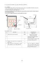
Water sensor
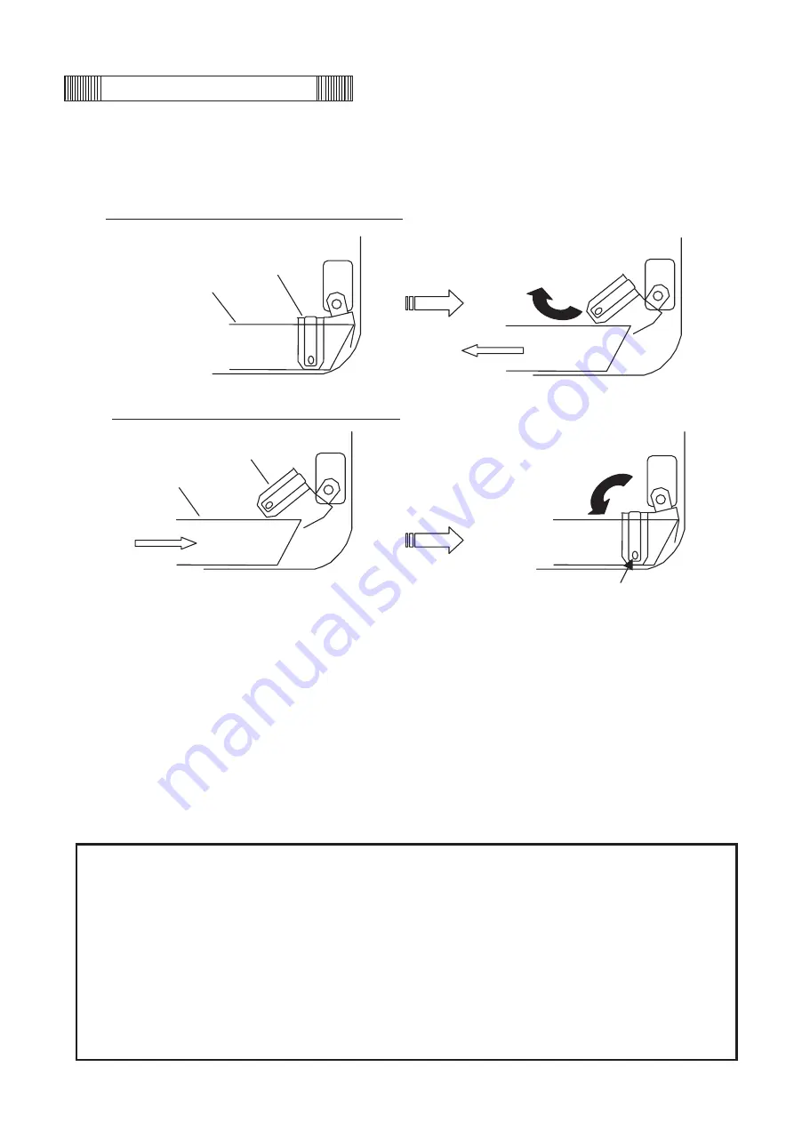
This Incubator is equipped with a water level sensor for the humidifying pan. The sensor is set automatically
when the humidifying pan is installed. Take care not to damage the sensor when removing or installing the
humidifying pan.
When the humidifying pan is removed (side view)
When the humidifying pan is installed (side view)
Note:
Make sure that the humidifying pan is all the way to the back and that the sensor comes down when you
install the humidifying pan.
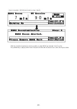
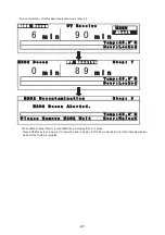
• Lift the sensor before installing the humidifying pan if the sensor is in the lower position after maintenance.
• When installing the humidifying pan, make sure that the pan is set properly and that sensor comes down into
the pan. “RH PAN” will be displayed in reverse video in the status display field on LCD panel if the sensor
does not come down completely. If necessary, set the pan again in the proper location.
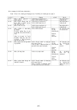
• The sensor detects the water level every 30 minutes and just after the outer door is closed. It takes several
seconds to detect the water level. Therefore, “RH PAN” may displayed in reverse video several times in the
status display field on LCD panel after the outer door is closed even when the humidifying pan is full.
CAUTION
Foreign particles on the water surface can adhere to the water level sensor and fittings by capillary action
because the sensor is always in the water. The adhered foreign particles degrade sensor performance and
“RH PAN” may be displayed in reverse video in the status display field on LCD panel even though there is
sufficient water in the humidifying pan. Be sure to wipe OFF any dirt on the water level sensor with
disinfectant alcohol whenever you change the humidifying water. When cleaning the sensor, take care not
to apply excessive force to the lead wires.
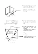
When cleaning the sensor, mainly wipe OFF dirt on the right side of photo sensor (where red LED is lit when
the door switch pressed).
Sensor
Pan
Pan
Sensor
Photo sensor
Summary of Contents for MCO-19M
Page 7: ... 4 Dimensions Power cord ...
Page 16: ...Wiring diagram 13 ...
Page 17: ...Circuit diagram Main PCB 14 ...
Page 18: ... LCD PCB 15 ...
Page 110: ...MCO 19M UVH MCO 19M UV MCO 19M Multi Gas Incubator INSTRUCTION MANUAL 107 ...
Page 112: ...CONTENTS SPECIFICATIONS P 74 PERFORMANCE P 75 SAFETY CHECK SHEET P 76 109 2 ...
Page 183: ...Fig A Stacking plate B Stacking plate A Protective sticker Front panel Hook Front 180 73 ...
Page 187: ...SANYO Electric Co Ltd Printed in Japan DC3186 150B ...

