AUTOMATIC CO
2
CYLINDER CHANGEOVER
An automatic CO
2
cylinder changeover system (MCO-21GC) is available as an optional accessory. This
system switches the gas supply lines when one CO
2
gas cylinder becomes empty.
Note:
The installation of the MCO-21GC must be performed only by qualified service personnel.
Install the MCO-21GC and then perform the following procedure
1.
Connect 2 gas tubes to connecting ports A/B for CO
2
gas pipe. Connecting ports for CO
2
gas pipes are
located on the left back of the Incubator. (Refer to page 9).
Note:
Only port A can be used when the MCO-21GC is not installed. There will be 2 ports, ports A and B,
after the MCO-21GC is installed.
2.
Connect a CO
2
gas cylinder equipped with a gas pressure regulator to each gas tube. Refer to page 16
for information on connecting the gas cylinders. (“Gas cylinder A” is the CO2 gas cylinder connected to
the connecting port A for CO
2
gas pipe, and “gas cylinder B” is the CO2 gas cylinder connected to the
connecting port B for N
2
/O
2
gas pipe.)
3.
Open the valves of both gas cylinders.
4.
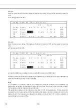
The current CO
2
gas supply line is displayed on the Top Display.
(“A” and “B” will be displayed only when the MCO-21GC is installed. Nothing will be displayed if
MCO-21GC is not installed.)
5.
The MCO-21GC detects that there is no more CO
2
gas in a cylinder when the CO
2
density in the
chamber does not increase for a while even after opening the CO
2
gas valve in the Incubator. It switches
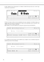
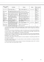
the gas supply line when it detects that there is no more gas. At that time, the following indications of
switching the gas cylinder are provided.
Message display field
Display of gas supply
When CO
2
gas supply line switches
automatically (Only when MCO-21GC
is installed)
Err01: CO
2
Gas Empty is
displayed.
The character for gas supply line
that is empty blinks.
The gas supply line that is
currently being used is displayed
in reverse video.
●
To silence the buzzer, press the BUZZER Key. The alarm condition is cleared and normal operation
continues.
Current CO
2
gas supply line
5
.
1
T e m p
3 7 . 0
o
C C O 2
5 . 0 %
A
B O 2 5 . 0
%
A
B
2
3
4
5
S
t a t u s
6
O K
7
37
.
0
5
.
0
5
.
0
- 174 -
67
Summary of Contents for MCO-19M
Page 7: ... 4 Dimensions Power cord ...
Page 16: ...Wiring diagram 13 ...
Page 17: ...Circuit diagram Main PCB 14 ...
Page 18: ... LCD PCB 15 ...
Page 110: ...MCO 19M UVH MCO 19M UV MCO 19M Multi Gas Incubator INSTRUCTION MANUAL 107 ...
Page 112: ...CONTENTS SPECIFICATIONS P 74 PERFORMANCE P 75 SAFETY CHECK SHEET P 76 109 2 ...
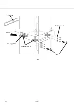
Page 183: ...Fig A Stacking plate B Stacking plate A Protective sticker Front panel Hook Front 180 73 ...
Page 187: ...SANYO Electric Co Ltd Printed in Japan DC3186 150B ...

