


- 247 -
-
247
-
C
h
ap
ter
7
7-3
Description of Functions
Sequence 6
:
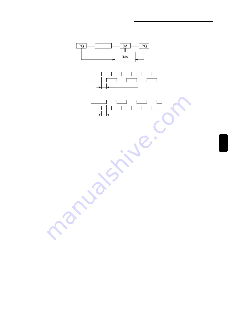
Setting of PG pulse A-B polarity reversal (F8125)
During connections of PG input terminal, the relationship between rotating direction and phase
A/B must be connected as the following figure.
Load side
①
Inverter forward command and PG pulse phase difference.
Phase A 90° phase lead
②
Inverter reverse command and PG pulse phase difference.
Phase A 90° phase lag
In case of forward command: To phase B, phase A is 90° phase lead.
In case of reverse command: To phase B, phase A is 90° phase lag.
The function of PG pulse A-B polarity reversal (F8125) is used to switch the signal rather than change the
wiring in case that the relationship between the rotating direction and phase A/B is reversed after connecting
the PG sensor signal wiring.
Note
1:
With this function, the speed can be controlled without changing the connection of phase A and phase B. If
possible, please use this function based on the correct connection of phase A and phase B.
Note
2:
When using the functions of zero-servo (F8119) and position control, disable the function of PG pulse A-B polarity
reversal (F8125=0). If this function is enabled, the control will not be exact.
Sequence 7: Setting of control gain
● Setting of control gain during speed control ASR
Example) When control response of proportional gain is 50rad/s and the integral time is 100ms,
Speed control ASR proportional gain: F6010=25% (200rad/s at 100%)
Speed control ASR integral time: F6011=0.100s (100ms).
Note: The initialized value of speed control ASR proportional gain varies according to the different settings of
motor category is F5001. Even standard motor gain is set, there still may be large gain for different motors.
Therefore, when initially running the motor, please adjust the speed control ASR proportional gain.
● Setting of control gain during position control
Example) When control response of position control gain is set with 20rad/s, speed control ASR proportional
gain is set with 100rad/s and integral time is set with 100ms,
Position control gain: F8110=20rad/s
Speed control ASR proportional gain: F6010=50% (200rad/s at 100%)
Speed control ASR integral time: F6011=0.100s (100ms).
Note 1: The initialized value of position control gain is set by 1 rad/s, however, according to different motors, too
large gain may still happen. Therefore, please adjust the speed control ASR proportional gain during initial
running of the motor.
Note 2: If the setting of speed control gain is too large, over adjustment may happen on target position, therefore,
please adjust the gain while observing the motor rotation and the motor current.
Note 3: In case there is a vibration during motor rotating, please set speed control ASR integral time to 0 or
smaller than the current value. When setting to ―47‖ (P control signal, PC) through multi-function input
terminals, the speed control can be treated as proportional control for input signal.
Reference parameter
F1001 (motor control mode selection)
F1414-F1421 (selection of input terminal DI1-DI8)
PG signal Phase A & B
at load side
PG signal Phase A & B
at
motor side
Phase A
Phase A
Phase B
Phase B
Summary of Contents for SVCO6
Page 1: ...High Performance Vector Control Inverter Instruction Manual SANKEN ELECTRIC CO LTD ...
Page 2: ......
Page 324: ... 322 Memorandum ...
Page 325: ......