


- 246 -
7-3
Description of Functions
Example) In case of a motor with 4 poles, 380V and 3.7kW
Please set F5001=44_3.7
Note: If the settings of the motor and F5001 are not appropriate, the speed control or position control will not be carried
out correctly. Please set suitable values in F5001.
Sequence 2: Selection of motor control mode (F1001)
.
The setting of operation mode for speed control, torque control or position control with PG sensor.
Example) According to the selected control mode, please make the following settings with function code F1001.
F1001=3: speed control (vector control of speed sensor)
F1001=5: torque control (vector control of speed sensor)
F1001=6: position control (vector control of speed sensor)
Sequence 3: Selection of input method for PG sensor signal (F8109)
Please select the PG sensor signal used by F8109 (PG output formation selection). The followings are
specifications for PG sensors corresponding to each setting value.
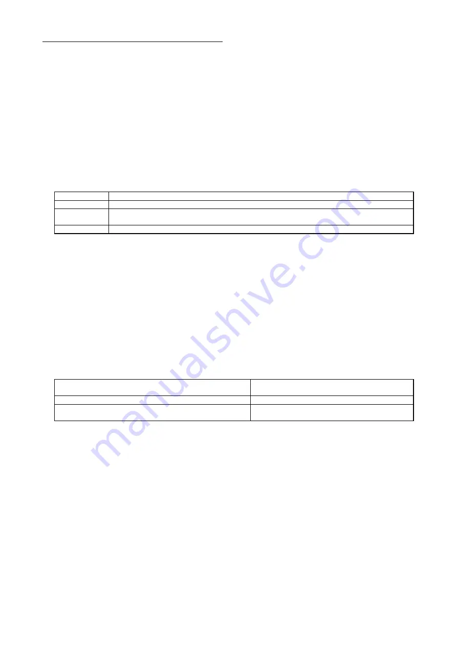
F8109
Specification
1
Open collector output (power voltage 24V) Voltage output signal-phase, two-phase (voltage output 24V)
2
Open collector output (active voltage 24V, 12V) Voltage output signal-phase, two-phase (voltage output
24V, 12V)
3
Bus driver output
※
The maximum input pulse frequency will be 491.52kHz in any mode.
Note 1:
The standard PG signal input will be open collector/push-pull, the power supply will only correspond to PG
sensor of 24V. When using PG sensors beyond the specification described here, options must be prepared
additionally (SC-PG).
Note 2:
If the function code contents and terminal connections are different, ―OCx‖ (over-current) and other alarms may
happen.
Sequence 4: Setting of number of PG pulses (F8122)
Please set the number of pulses per revolution for the PG sensor used in F8122 (number of PG pulses).
It can be set within the scope of 20-2048 pulses. (Factory preset is 1000 pulses)
Example) When the number of PG pulses is 512PPR,
Please set F8122=512.
Note: If the number of PG pulses is set falsely, the correct control will not be able to be carried out. The following table
shows the examples of actions during false setting.
Example for false setting of number of PG pulses
(when number of PG pulses is 1000 PPR)
Rotating speed
1000 PPR→500PPR
Stable when the speed is lower than command speed
1000 PPR→2000PPR
Stable when the speed is higher than command speed
(use upper frequency limit F1007 to ensure stable)
Sequence 5: Setting of PG pulse multiplication value (F8108)
Set the PG pulse multiplication value. Through this setting, the pulse count per revolution will be
multiplied by using the setting of multiplication value, therefore improving the control precision.
Example) In case of a setting with 4 multiplications
F8108=3 (using the default setting)
Note 1: When using a setting with 4 multiplications, please be sure to input the two phases of phase A and phase B.
Note 2: Even when the multiplication is changed, the motor speed will not be changed. Please set the pulse number on the
encoder equal to the pulse number of F8122.
Note 3: Since the setting value of F8122 x multiplication value of F8108 is not the pulse number on the encoder, special
attentions must be paid. (F8122 and F8108 are different functions). For example, when using an encoder of 1000
PPR, please set F8122=1000. The setting of F8122=500 and F8108 will influence the normal operation.
Summary of Contents for SVCO6
Page 1: ...High Performance Vector Control Inverter Instruction Manual SANKEN ELECTRIC CO LTD ...
Page 2: ......
Page 324: ... 322 Memorandum ...
Page 325: ......