


- 207 -
-
207
-
C
h
ap
ter
7
7-3 Description of Functions
【
Command Value of PID Control
】
F3001
PID1 command value input switching
F3101
PID2 command value input switching
F3013
PID1 command value gain
F3113
PID2 command value gain
F3019
Frequency corresponding to PID1
control maximum command value
F3119
Frequency corresponding to PID2
control maximum command value
The function to select the command value of PID control.
The function to select control command value, F3001 for PID1 and F3101 for PID2.
● Select the following PID command value in the setting of F3001/F3101.
· F3001/F3101=1: Frequency
The 1st speed frequency selected by F1002 and the frequency according to multi-speed command are the
command values.
· F3001/F3101=2
-
10: various analog input values (VIF1
-
VIF3)
The settings of various analog input values (VIF1
-
VIF3) are the command values.
Analog input is the same as normal frequency, the input value will be switched into frequency by gain
frequency and bias frequency of F1401
-
F1406, this frequency will be the command value used for PID control.
· F3001/F3101=11: use setting values of F3017 (PID1)/F3117 (PID2) as the command values.
The setting values of F3017 (PID1)/F3117 (PID2) will be switched into frequency by the setting values of
F3019 (PID1)/F3119 (PID2).
The maximum value (6000) of F3017 (PID1)/F3117 (PID2) will be switched into the frequency set by F3019
(PID1)/F3119 (PID2).
Example) When F3017=3000 and F3019=60Hz, the command value of PID will be 30Hz.
· F3001=99: pulse train input
F1002=25: same as pulse train, the pulse train input from external is the command value.
About the pulse train input, please refer to the pulse train function of F1002.
● Each PID command value can be gained by F3013 (PID1)/F3113 (PID2).
● Each PID command value will be limited according to the upper frequency limit after the gain, then
acceleration/deceleration will be processed.
When PID command value is beyond the frequency setting, the acceleration/deceleration time will be based on
reference frequency for acceleration/deceleration: F1011 is the reference, run the operation according to 3rd
acceleration time: F1014, 3rd deceleration time: F1018.
Note
1:
The PID control of acceleration/deceleration (beyond the frequency setting) will share the 3rd
acceleration/deceleration time used in normal operation, this is a fixed use.
Note
2:
During the 3rd acceleration time: F1014, when any one of F1018 during 3rd deceleration time =0, the
acceleration/deceleration will not be carried, the PID command target value will be directly used as PID
command value.
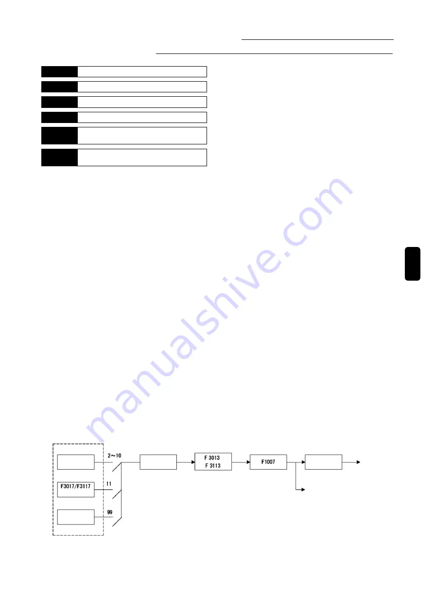
The following shows the formation of PID command value.
Gain
Limiter
Analog value
Upper frequency limit
Setting
Pulse train
[Function code for frequency switching]
Analog value: F1401
-
F1406
Setting of function code: F3019/F3119
Pulse train: F1002=25
PID command value input switching
F3001/F3101
Frequency
switching
Acceleration
/Deceleration
PID command
value
Fi
PID command target value Ft
Summary of Contents for SVCO6
Page 1: ...High Performance Vector Control Inverter Instruction Manual SANKEN ELECTRIC CO LTD ...
Page 2: ......
Page 324: ... 322 Memorandum ...
Page 325: ......