Malfunction and Remedies
Hydraulic valves
519 / 564
2
5
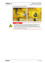
Once the repair work is completed, the spring-loaded actuator must be activated as
follows:
– Unscrew again the emergency release nut with the ring wrench (
5
) counterclock-
wise with noticeable resistance.
– The housing must be closed using the screw-on cover again.
– After completing all work, perform a brake test.
ADVICE
The basic setting of the brake is not affected by the emergency release process!
8.12
Hydraulic valves
All hydraulic valves are electrically controlled. Problems with solenoid valves may be
detected using specific test cables, which are supplied with each machine. These test
cables may only be connected to the solenoid valves by trained and instructed spe-
cialist personnel.
Should an electrically controlled valve malfunction, then in any case, without excep-
tion, call in a specialist. Never try to shake the solenoid valve concerned to remedy
possible contact problems or a possible line break. If the valve is suddenly opened
during such tries, then the person concerned may suffer deadly injuries.
WARNING
Searching and remedying malfunctions on all components of the hydraulic system is
exclusively the task of trained specialists. We expressly warn of tries to repair or self-
performed tests on hydraulic valves under electro-magnetic control. If during such
tests or tries to repair, parts of the hydraulic system are suddenly put under pressure,
then this may trigger unwanted machine movement. This may pinch or even crush
people or body parts.
Summary of Contents for Tiger 6
Page 3: ...Contents 3 564 Contents...
Page 4: ...Contents 4 564...
Page 13: ...Preface 13 564 1 Preface...
Page 14: ...Preface 14 564...
Page 22: ...Safety 22 564...
Page 23: ...Safety 23 564 2 Safety...
Page 24: ...Safety 24 564...
Page 41: ...General View and Specifications 41 564 3 General View and Specifications...
Page 42: ...General View and Specifications 42 564...
Page 53: ...General Description 53 564 4 General Description...
Page 54: ...General Description 54 564...
Page 57: ...Operating Components 57 564 5 Operating Components...
Page 58: ...Operating Components 58 564...
Page 98: ...Operation 98 564...
Page 99: ...Operation 99 564 6 Operation...
Page 100: ...Operation 100 564...
Page 226: ...Operation Defoliator 226 564 RIS defoliator RES defoliator...
Page 291: ...Operation Infeed conveyor 291 564 2 1 1 Infeed conveyor control block...
Page 299: ...Operation Strainer wheels turbines 299 564 4 Rpm strainer wheels...
Page 325: ...Operation Bunker unloading 325 564 6 19 Bunker unloading...
Page 361: ...Maintenance and Service 361 564 7 Maintenance and Service...
Page 362: ...Maintenance and Service 362 564...
Page 418: ...Maintenance and Service Defoliator 418 564 Defoliator in the maintenance position...
Page 475: ...Malfunction and Remedies 475 564 8 Malfunction and Remedies...
Page 476: ...Malfunction and Remedies 476 564...
Page 528: ...Lists Tables Plans Diagrams Maintenance Verification 528 564...
Page 558: ...558 564...
Page 559: ...Index 559 564 10 Index...
Page 560: ...Index 560 564...

