Operation
Lifter
251 / 564
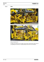
2
1
3
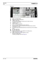
Lifting unit, shown without protective cover for a better overview.
(1)
Depth-control roller/wheel
(2)
Share body
(3)
Lifting rollers
The complete lifting unit (shaking shares, paddle, depth-control shaft, lifting rollers,
pinching roller) is driven hydraulically.
Applied to all lifters:
Lifting rollers one to six are driven by the left front lifter gear unit. The two short lifting
rollers on the right are driven by the right rear lifter gear unit.
The two short lifting rollers on the left are driven by the left rear lifter gear unit. For all
lifters the direction of rotation of the last lifting shaft can be changed from the driver’s
seat. This gives a pinch roller effect. This improves the cleaning result.
The operating depth of the lifting shares in the ground (share depth adjustment) and
the distance of the lifting rollers from the ground (height adjustment of the roller move-
ment) can be conveniently set from the driver's seat.
Power is transferred between the drive and the long lifting rollers via a polyamide plug-
in connector. The plug-in connector is screwed into the left end of the roller for all lift-
ing rollers.
As optional equipment, the lifter may be fitted with lifting shafts having a larger diame-
ter than the standard shafts. This largely avoids beet losses for small sugar beets. But,
simultaneously, soil separation in the lifter is reduced.
The depth-control shaft guides the lifting shares to the depth set and simultaneously,
using the forced intake (three stable rubber paddles for each row of beets), supports
the sugar beet flow from the shares to the lifting rollers.
The depth-control shaft is hydraulically driven on both sides. The speed of the depth-
control shaft depends on the driving speed, but may be changed by the driver.
Summary of Contents for Tiger 6
Page 3: ...Contents 3 564 Contents...
Page 4: ...Contents 4 564...
Page 13: ...Preface 13 564 1 Preface...
Page 14: ...Preface 14 564...
Page 22: ...Safety 22 564...
Page 23: ...Safety 23 564 2 Safety...
Page 24: ...Safety 24 564...
Page 41: ...General View and Specifications 41 564 3 General View and Specifications...
Page 42: ...General View and Specifications 42 564...
Page 53: ...General Description 53 564 4 General Description...
Page 54: ...General Description 54 564...
Page 57: ...Operating Components 57 564 5 Operating Components...
Page 58: ...Operating Components 58 564...
Page 98: ...Operation 98 564...
Page 99: ...Operation 99 564 6 Operation...
Page 100: ...Operation 100 564...
Page 226: ...Operation Defoliator 226 564 RIS defoliator RES defoliator...
Page 291: ...Operation Infeed conveyor 291 564 2 1 1 Infeed conveyor control block...
Page 299: ...Operation Strainer wheels turbines 299 564 4 Rpm strainer wheels...
Page 325: ...Operation Bunker unloading 325 564 6 19 Bunker unloading...
Page 361: ...Maintenance and Service 361 564 7 Maintenance and Service...
Page 362: ...Maintenance and Service 362 564...
Page 418: ...Maintenance and Service Defoliator 418 564 Defoliator in the maintenance position...
Page 475: ...Malfunction and Remedies 475 564 8 Malfunction and Remedies...
Page 476: ...Malfunction and Remedies 476 564...
Page 528: ...Lists Tables Plans Diagrams Maintenance Verification 528 564...
Page 558: ...558 564...
Page 559: ...Index 559 564 10 Index...
Page 560: ...Index 560 564...


