PAGE 90
OPERATOR’S MANUAL ULTRA GUIDANCE PSR ISO
CHAPTER
PSR SONIC
6.2.
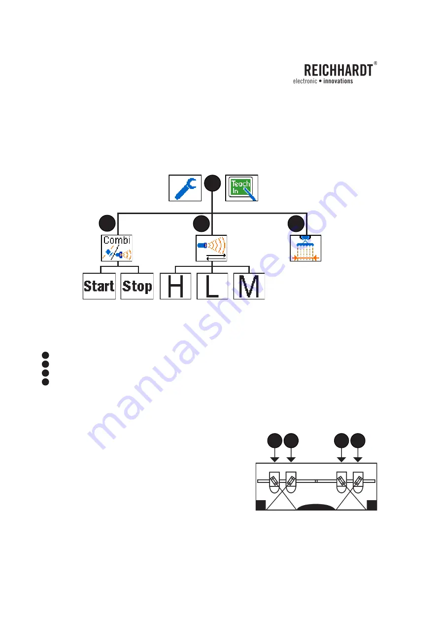
Menu structure PSR SONIC
A
= Main Menu PSR SONIC
B
= Sample Spacing PSR SONIC
C
= Working width (When actively coupled)
D
= Combined PSR SONIC – PSR SKY
6.3.
Adjusting Sensors
The Ultra sound sensors are supported by incrementally adjustable
carrier arms. They are manually adjustable to a degree of +/- 75
of vertical.
The carrier arms are mounted to a main carrier frame and are
easily adjustable to fit the track of the respective vehicle.
In order to change a sensor direction, loosen the nut on the back
side of the sensor mount, reach under the cover and rotate the
sensor to the desired direction. Make sure it matches one of the
holes provided.
Picture 148:
Menu structure PSR SONIC
Picture 149:
Sensor positions
3
4
1
2
B
A
D
C


