


FASTCAM-APX RS Hardware Manual
-92-
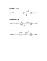
3.11.2. Output of Trigger Signals to External
Equipment
The APX RS can output trigger signals to drive external equipment and devices. The
output signals are provided from the TRIGGER SW OUT and TRIGGER TTL OUT
connectors. In addition, other trigger output signals are available from the GENERAL
OUT connector by setting up the circuit as necessary.
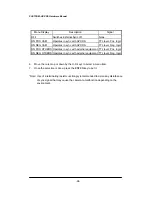
The following table shows the output connectors and the relevant output signals.
Connector
(Output)
Menu
Setting
Signal
Delay
(Approx.)
TRIGGER SW
OUT
None
Contact signal
5 nsec
TRIGGER TTL
OUT
None
CMOS (74ACT541
buffered) Output,
Positive logic
2.7 µsec
TRIGGER
POS
CMOS (74ACT541
buffered) Output,
Positive logic
55 nsec
GENERAL
OUT
TRIGGER
NEG
CMOS (74ACT541
buffered) Output,
Negative logic
70 nsec
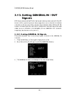
*Note: For output trigger signals from GENERAL IN, the GENERAL IN circuit must be
set up for the type of the input signal from the menu in advance. See Section
3.13.2. GENERAL OUT for details.


