FASTCAM-APX RS Hardware Manual
-90-
3.11. External Trigger Input
The APX RS can operate in response to external triggers that are provided depending
on the needs of each application.
This section discusses the different kinds of external triggers and how to set up the
system for each of them.
3.11.1. Input of External Trigger Signals
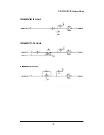
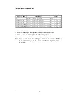
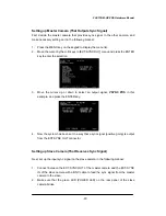
The trigger signals that are used on the APX RS and the corresponding input
connectors are shown below.
Connectors (Input)
Menu Setting
Signals
TRIGGER SW IN
None
Contact signal
Trigger on CLOSURE
TRIGGER TTL IN
None
Optical isolator input
Positive logic,
5V, 15mA(recommended)
7V, 23mA(maximum)
TRIGGER POS
TTL level, Positive logic
5V(maximum)
GENERAL IN
TRIGGER NEG
TTL level, Negative logic
5V(maximum)
Contact signal, Trigger on CLOSURE
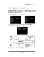
*Note: For input trigger signals for GENERAL IN, the GENERAL IN circuit must be set
up for the type of the input signal from the menu in advance. Refer to Subsection 3.13.1.
Setting GENERAL IN Signals for details.
*
Note: Do not input any trigger signals other than contact signals to TRIGGER SW IN,
otherwise the camera may be seriously damaged.
*
Note: Do not apply trigger signals of excessive voltage or current to TRIGGER SW IN
or GENERAL IN, otherwise the camera may be seriously damaged.


