Installation
4-29
AC30V Variable Speed Drive
APPLICATION 4: PID CONTROL
RELAY 01
(X14/01)
(X14/02)
RELAY 02
(X14/03)
(X14/04)
ANIN 01
(X11/01)
ANIN 02
(X11/02)
RAMP
0486
Acceleration Time
PROCESS SETPOINT
PROCESS FEEDBACK
RUNNING
NOT TRIPPED
CURRENT LIMIT
V/F SHAPING
CT
VT
V
F
PWM CONTROL
I FDBK
F
V
F
V
0484
Seq Stop Method
DIGIN 01
(X13/02)
DIGIN 02
(X13/03)
DIGIN 03
(X13/04)
DIGIN 04
(X12/01)
DIGIN 05
(X12/02)
DIGIN 06
(X12/03)
DIGIN 07
(X12/04
SEQUENCING LOGIC
RUN
PID INTEGRAL DEFEAT
NOT STOP
NOT COAST STOP
NOT QUICKSTOP
TRIP RESET
PID ENABLE
0422
Vhz Shape
0457
Base Frequency
0447
Fixed Boost
0455
Rated Motor Current
FEEDBACKS
ANOUT 01
(X11/03)
ANOUT 02
(X11/04)
SPEED DEMAND
MOTOR CURRENT
Application 4:
“Process PID”
EASY TUNING FOR SETPOINT/FEEDBACK
CONTROL APPLICATIONS REGULATING
VOLUME OR PRESSURE, SUCH AS AIR
HANDLING OR PUMPING
Speed
Setpoint
Pressure or Volume Feedback
Transducer
PID CONTROL
1928
Proportional Gain
1929
Integral TC
1930
Derivative TC
1931
Output Filter TC
1932
Output Pos Limit
1933
Output Neg Limit
1934
Output Scaling
MIN /MAX SPEED
1264
Ref Min Speed Clamp
1265
Ref Max Speed Clamp
0487
Deceleration Time
0504
Stop Ramp Time
0508
Quickstop Ramp Time
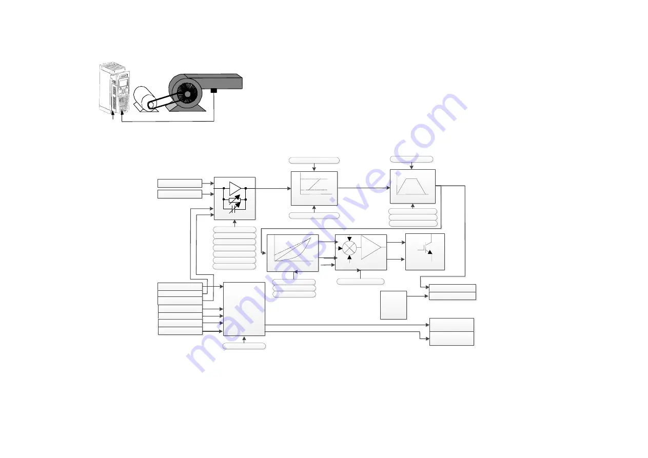
PID Control Application
A simple application using a Proportional-Integral-Derivative 3-term controller. By default the setpoint is taken from AIN1, with feedback signal
from the process on AIN2, scaling parameter 1939 swaps the routing of AIN1 & 2. The scale and offset features of the analogue input blocks may
be used to correctly scale these signals. The difference between these two signals is taken as the PID error. The output of the PID block is then
used as the drive setpoint.


