


9-3
Section
Creating the Sample Data
365
Setting the touch switch outline
(1) Select [Objects] (menu bar)
→
[Touch Switch]. (Refer to
6-8 Touch
Switches
.)
(2) Create the outline of the [Monitor Screen] button by dragging the mouse
on the data creation screen.
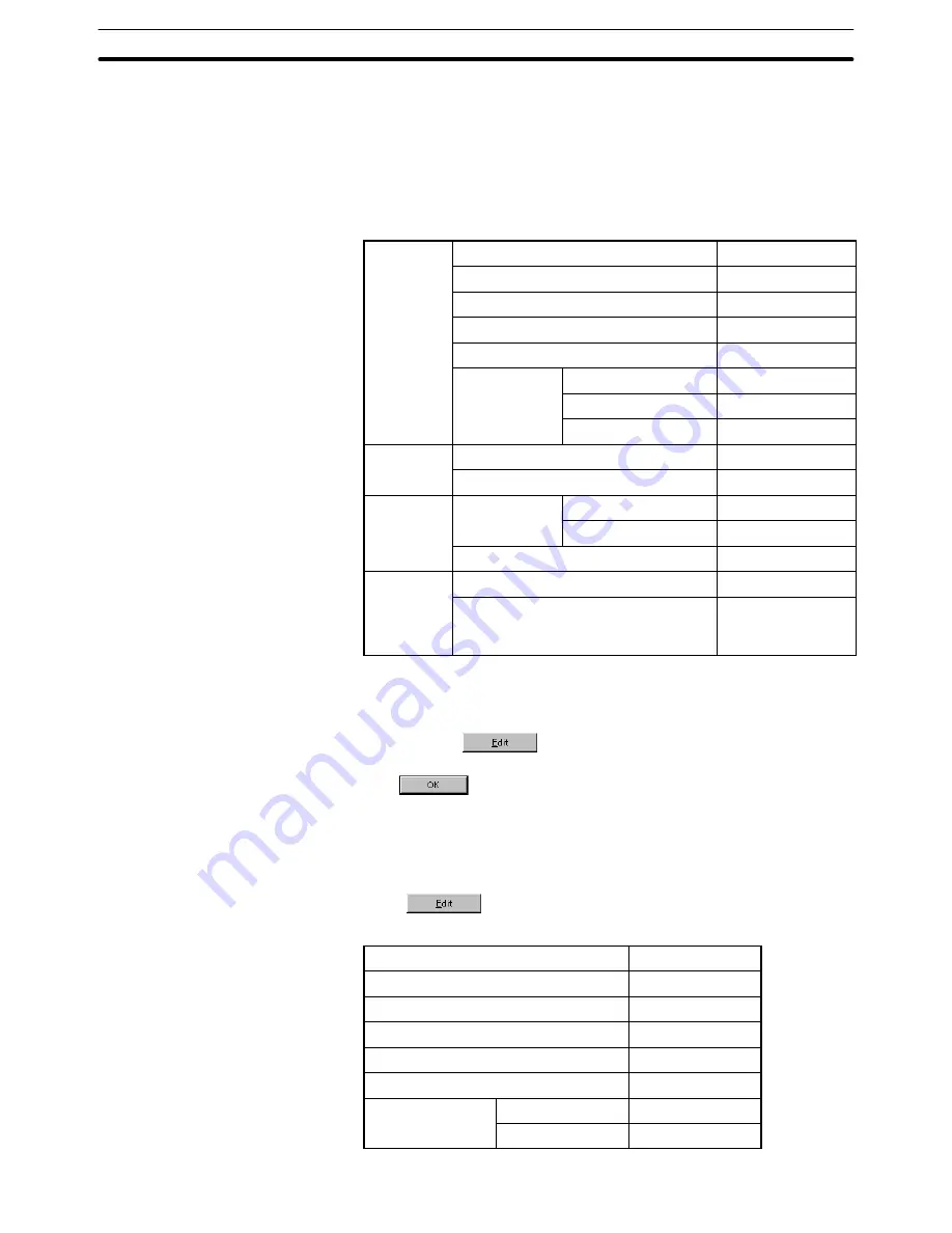
(3) Set the properties as shown below.
General
Position
––
Size
––
Frame
Shape
3-Dimension
Show ON State
––
Color
Frame
White
ON
White
OFF
Transparent
Settings
Function
Switch Screen
Screen No.
2
Light
Function
Address
PC (PLC) Address
––
Function
I/O Comments
––
Lamp Attribute
Light
Label*1
Label
Description
Monitor Screen
(Refer to the fol-
lowing)*2
*1: For the NT21 and NT31, NT31C, NT631 and NT631C with “-V2” or
later models, multiple lines of label, On Off static label, numeral/
string display label can also be set.
*2: Click the
Button to set the label.
After completing the setting, go to the next step by clicking the
Button.
*3: For the NT21 and NT31, NT31C, NT631 and NT631C with “-V2” or
later models, it is possible to set an interlock bit that can enable/dis-
able the operations.
Setting the touch switch label
(4) Press
in the general property of a touch switch and set the la-
bel properties as shown below.
Description
Monitor Screen
Position
––
Font Type
Standard
Scale
2
2
Smoothing
Attribute
Standard
Color
Foreground
White
Background
Transparent
Summary of Contents for NT-SERIES - SUPPORT TOOL FOR WINDOWS V4
Page 1: ...Cat No V061 E1 06 Support Tool for Windows Ver 4 NT Series OPERATION MANUAL...
Page 2: ......
Page 3: ...NT series Support Tool for Windows Ver 4 j Operation Manual Revised July 2010...
Page 4: ...iv...
Page 6: ...vi...
Page 14: ......
Page 80: ......
Page 94: ......
Page 338: ......
Page 422: ......
Page 458: ......
Page 478: ......
Page 502: ......
Page 508: ......
Page 532: ......
Page 556: ......
Page 560: ......
Page 562: ......
Page 564: ......
Page 570: ......
Page 572: ......
Page 584: ......
Page 590: ......
Page 592: ......
Page 593: ......


