


90
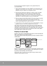
If the system gain (SEt-42) is raised, the overall
gains increase and the response improves. If this
value is changed, the five basic gains change, and
the inertia ratio is referred to in this process. If the
value is set too high for the load condition,
vibration or noise can be generated.
By setting SEt-42, basic gains are changed by referring to the inertia
ratio (SEt-66). As the value is set higher, the response improves. But if
the value is too high for the load condition, vibration or noise can be
generated.
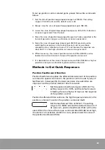
The function of the system bandwidth
(SEt-69) is
the same as the function of the system gain (SEt-
42), but while the system gain changes according
to the inertia ratio, the system bandwidth remains
parameter even if the inertia ratio changes.
When the inertia ratio is changed by auto tuning or user, change the
system and basic gain refering to SEt-69 and inertia ratio.
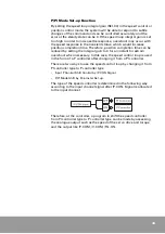
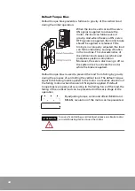
Torque Control Gain
Torque control gains include vibration suppression filter and torque
command filter gain. The diagram below shows the application
process of torque control-related gains.
Vibration suppression filter restrains the vibration caused by the load’s
resonance when the load system resonates in a certain frequency
band. If properly set, it allows other gains to be raised, so that the
stability and response of the overall system are improved greatly. But
if it is set incorrectly, it can cause vibration or noise.
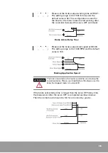
Set vibration suppression filter at SEt-47. The
setting range is 0 to 10000 Hz, and the default value
is 10000.
Torque command filter limits the high frequency element in the torque
command. By limiting the high frequency element higher than the
preset level, torque command itself can be softened to reduce
vibration and noise.
ATTENTION
The value set last takes priority in the gain set-up. For
instance, even after the speed loop proportional gain is
changed by setting the system gain (SEt-42), if the speed loop
proportional gain (SEt-02) is set again, this value is valid.
Summary of Contents for CSDP Plus
Page 1: ...Maximum Value for OEMs SM CSDP Plus Servo Drive User Manual...
Page 16: ...18...
Page 30: ...32 Higher Control Connector CN1 Circuit Diagram...
Page 33: ...35 Compact Absolute Encoder Wiring Serial Encoder Wiring...
Page 38: ...40...
Page 120: ...122...
Page 179: ...181 Speed Torque Curve...
Page 180: ...182...
Page 183: ...185 Speed Torque Curve...
Page 184: ...186...
Page 187: ...189...
Page 190: ...192 Speed Torque Curve...
Page 193: ...195...
Page 196: ...198...
Page 201: ...203...
Page 204: ...206...
Page 207: ...209...
Page 210: ...212...
Page 215: ...217...
Page 230: ...232...
Page 252: ...254...
Page 253: ......