


172
SEt-64 Forward Torque Offset
•
Setting range: 0 to 100%
•
User Default: 0
•
Changes while the servo is OFF
Set this parameter in cases where the load moves upward vertically
when the motor revolves in the forward direction. This can
supplement the problem of a falling vertical load when the mechanical
brake is released as the servo is ON.
SEt-65 Reverse Torque Offset
•
Setting range: 0 to 100%
•
User Default: 0
•
Changes while the servo is OFF
Set this parameter in cases where the load increases when the load
moves along the vertical axis and the motor revolves in the reverse
direction. This can resolve the problem of a falling load when the
mechanical brake is released after the servo is ON in case of a
vertically operating load.
SEt-66 Load Inertia Ratio
•
Setting range: 0 to 600 0.1 times
•
User Default: 30
•
Changes while the servo is OFF
The load inertia ratio estimated by auto tuning is set automatically.
In tuning, the inertia ratio should be
considered first for the optimum
performance of the motor connected to
the servo drive. The inertia ratio is the
ratio of the inertia of the load to that of
the motor’s rotor.
If the inertia of rotor is 3 gf.cm.s
2
and the inertia of load is 3 gf.
cm.
s
2
,
inertia ratio is 10 times.
Inertia Ratio = Inertia of the Load/Inertia of the Motor’s Rotor
Summary of Contents for CSDP Plus
Page 1: ...Maximum Value for OEMs SM CSDP Plus Servo Drive User Manual...
Page 16: ...18...
Page 30: ...32 Higher Control Connector CN1 Circuit Diagram...
Page 33: ...35 Compact Absolute Encoder Wiring Serial Encoder Wiring...
Page 38: ...40...
Page 120: ...122...
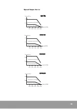
Page 179: ...181 Speed Torque Curve...
Page 180: ...182...
Page 183: ...185 Speed Torque Curve...
Page 184: ...186...
Page 187: ...189...
Page 190: ...192 Speed Torque Curve...
Page 193: ...195...
Page 196: ...198...
Page 201: ...203...
Page 204: ...206...
Page 207: ...209...
Page 210: ...212...
Page 215: ...217...
Page 230: ...232...
Page 252: ...254...
Page 253: ......


