


89
Setting Tuning Coefficient on online
To use online auto tuning, set the coefficient at the
fourth digit of SEt-58. Setting range is 0 to 9. If the
fourth position is not 0, online auto tuning function
will be used.
As the value is set higher, the system becomes
more sensitive to load fluctuation.
While online auto tuning is being used, please raise system gain (SEt-
42) if the response of the control loop drops and lower it if the system
makes noise or vibrates.
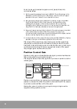
Gain Manual Set-up
To set up gains manually, please follow the command below.
1. Set the inertia ratio and system gain automatically executing offline auto
tuning.
2. If the response of control loop is lowered, raise the system gain value
.
If
the load system makes noise or vibrates, lower the set value until vibration
or noise stops.
If the load system is not composed of optimum combination by 1 and 2
above, adjust the gain minutely as 3, 4 and 5 hereunder.
3. Fine tune the value of each basic gain.
(Speed loop proportional gain, Speed loop integral gain, Position loop
proportional gain, Torque command Filter, Speed command Filter)
4. Fine tune the value of each applied gain.
(Position command filter, Vibration suppression filter, Position feedforward
gain, Position feedforward filter)
5. Set the four parameter required for tuning.
(P control shift switch, P control shift reference value, Speed bias
application range, Speed bias amount)
If the response drops after offline auto tuning, raise the system
bandwidth (SEt-69) a little and run offline auto tuning again. Secure
the maximum response by raising the system gain
(Set-42) to the level
before vibration or noise starts.
When the maximum response is secure while the
inertia ratio (SEt-66) is set accurately and the load
system has no vibration or noise, the system gain
can be set as high as possible and becomes the
bandwidth of the overall speed control loop.
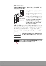
ATTENTION
If the load fluctuates radiply, online auto tuning coefficient
needs to be set high, but caution is needed because the
system can be momentarily unstable in an environment
where the load fluctuates excessively.
Summary of Contents for CSDP Plus
Page 1: ...Maximum Value for OEMs SM CSDP Plus Servo Drive User Manual...
Page 16: ...18...
Page 30: ...32 Higher Control Connector CN1 Circuit Diagram...
Page 33: ...35 Compact Absolute Encoder Wiring Serial Encoder Wiring...
Page 38: ...40...
Page 120: ...122...
Page 179: ...181 Speed Torque Curve...
Page 180: ...182...
Page 183: ...185 Speed Torque Curve...
Page 184: ...186...
Page 187: ...189...
Page 190: ...192 Speed Torque Curve...
Page 193: ...195...
Page 196: ...198...
Page 201: ...203...
Page 204: ...206...
Page 207: ...209...
Page 210: ...212...
Page 215: ...217...
Page 230: ...232...
Page 252: ...254...
Page 253: ......


