


6. APPLICATION OF FUNCTIONS
6 - 18
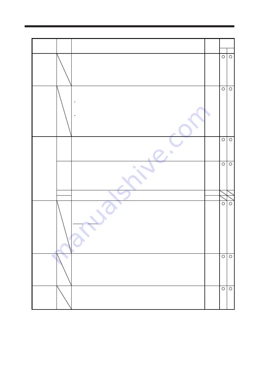
No./symbol/
name
Setting
digit
Function
Initial
value
[unit]
Control
mode
CP CL
6
*CIBSS
Cam
standard
position
(initial setting
value)
This is enabled when [Cam control data No. 3] is set to "1". Set the initial value of
the cam standard position in the output axis position unit.
The unit will be changed to [
μ
m], 10
-4
[inch], 10
-3
[degree], or [pulse] with the setting
of [Pr. PT01].
Setting range: -999999 to 999999
0
Refer to
Function
column
for unit.
7
*CICYS
Cam axis one
cycle current
value (initial
setting value)
Set the position to start the search processing to restore the cam axis one cycle
current value. Set this item when restoring the position of the return path with the to-
and-fro control cam pattern.
When [Cam control data No. 30] is set to "1"
The unit will be changed to [
μ
m], 10
-4
[inch], 10
-3
[degree], or [pulse] with the
setting of [Pr. PT01].
When [Cam control data No. 30] is set to "2"
The unit will be changed to [
μ
m], 10
-4
[inch], 10
-3
[degree], or [pulse] with the
setting of [Cam control data No. 14].
Setting range: 0 to [Cam control data No. 48] - 1
0
Refer to
Function
column
for unit.
14
*ETYP
Synchronous
encoder axis
unit
_ _ _ x Control unit
0: mm
1: inch
2: degree
3: pulse
0h
_ _ x _ Feed length multiplication
0: × 1
1: × 10
2: × 100
3: × 1000
This digit is disabled when [Cam control data No. 14] is set to "_ _ _ 2" or "_ _ _ 3".
0h
_ x _ _ For manufacturer setting
0h
x _ _ _
0h
15
*ECMX
Synchronous
encoder axis
unit
conversion:
Numerator
Set a numerator used to convert encoder pulses of the synchronous encoder axis
into the synchronous encoder axis unit.
Set the numerator within the following range.
1
16000
ECMX
ECDV
≤
≤
6000
Setting a value out of the range will trigger [AL. F6 Cam control warning].
When "0" is set, handle the numerator in the same way as when "1" is set.
Setting range: 0 to 16777215
0
16
*ECDV
Synchronous
encoder axis
unit
conversion:
Denominator
Set a denominator used to convert encoder pulses of the synchronous encoder axis
into the synchronous encoder axis unit.
Set a value within the range of [Cam control data No. 15].
Setting a value out of the range will trigger [AL. F6 Cam control warning].
When "0" is set, handle the denominator in the same way as when "1" is set.
Setting range: 0 to 16777215
0
30
*MAX
Main shaft
input axis
selection
Select an input axis of the main shaft input.
0: Disabled
1: Servo input axis
2: Synchronous encoder axis
0
Summary of Contents for MR-JE-100A
Page 49: ...2 SIGNALS AND WIRING 2 28 MEMO...
Page 73: ...3 DISPLAY AND OPERATION SECTIONS 3 24 MEMO...
Page 213: ...5 HOW TO USE THE PROGRAM 5 68 MEMO...
Page 275: ...6 APPLICATION OF FUNCTIONS 6 62 MEMO...
Page 355: ...8 TROUBLESHOOTING 8 8 MEMO...
Page 359: ...9 OPTIONS AND PERIPHERAL EQUIPMENT 9 4 MEMO...
Page 391: ...10 COMMUNICATION FUNCTION MITSUBISHI ELECTRIC GENERAL PURPOSE AC SERVO PROTOCOL 10 32 MEMO...


