About a Typical Pneumatic Circuit
6-12
KVAL Operation/Service Manual
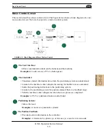
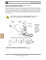
About a Typical Pneumatic Circuit
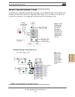
A control valve (solenoid) is used to drive cylinders to move different loads in the machine. The
solenoid if controlled by the PLC by applying a high voltage or a low voltage to a control coil.
Controls for example are: extending and retracting router, drill, clamping a door.
PLC
Output
High
Pressure
Air
Cylinder
Common
Control Circuit
ON
Measure
24 VDC here
Control Voltage
Should have High
Pressure air here
Cylinder
Control
Control
(Coil)
Input
Air
Input
Air
Output
Valve
Should have High
Pressure air on
Activated Output
Schematic Drawing of Pneumatic Circuit
Note:
Pre-2006
machines may
not contain the
24 Volt relay.
120 Vac is
directly fed into
the Control Coil.
Check the input
circuitry to the
Control Coil for
120 Vac.
Note:
In this
sample set-up,
Port A is nor-
mally closed
and Port B is
normally open. If
power is OFF,
air should be on
Port B.
FIGURE 6- 25.
Block Diagram of a Pneumatic Circuit
Summary of Contents for Edge-SS
Page 5: ...KVAL Edge SS Operation Service Manual ...
Page 12: ...KVAL Edge SS Line Operation Service Manual ...
Page 32: ...Safety Sign Off Sheet 1 20 KVAL Operation Service Manual ...
Page 35: ...Definitions 2 45 KVAL Operation Service Manual ...
Page 91: ...Definitions KVAL Operation Service Manual 2 56 ...
Page 109: ...System IT Administration 4 4 KVAL Operation Service Manual ...
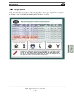
Page 142: ...Collet Torque Values 5 33 KVAL Operation Service Manual ...
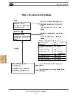
Page 143: ...Troubleshooting Electrical Problems 6 30 KVAL Operation Service Manual ...
Page 173: ......
Page 177: ......
Page 178: ......
Page 179: ......

