background image

Ch.3 Setup

< 99 >

DRYPRO Vstage MODEL 793 Installation Manual Ver.1.00 2004.11

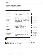
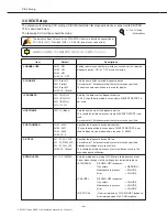
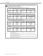
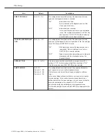
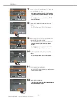
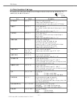
The relationship between communication between DRYPRO 793 and external devices according to

DICOM error level settings is shown below. 

Setting

DICOM Communication

Print Job

DRYPRO 793 Status Displayed 

Message

Registration

on External Diagnostic Device

STANDARD

NORMAL

α

READY

FAILURE

NORMAL

α

READY

N-ACTION

NORMAL

α

READY

In warming up, ready to print and tray empty statuses

(when the film empty notice is set to "OFF". Including the relation in film empty status.)

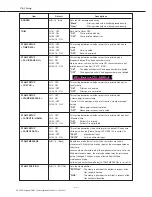
Setting

DICOM Communication

Print Job

DRYPRO 793 Status Displayed 

Message

Registration

on External Diagnostic Device

STANDARD

FAILURE

β

CHECK PRINTER

FAILURE

FAILURE

β

CHECK PRINTER

N-ACTION

NORMAL

α

READY

In user/service maintenance mode active statuses

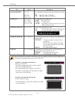
Setting

DICOM Communication

Print Job

DRYPRO 793 Status Displayed 

Message

Registration

on External Diagnostic Device

STANDARD

WARNING

β

FILM EMPTY

FAILURE

FAILURE

β

FILM EMPTY

N-ACTION

NORMAL

χ

READY

In tray empty status (With tray empty notification set to "ON.")

Setting

DICOM Communication

Print Job

DRYPRO 793 Status Displayed 

Message

Registration

on External Diagnostic Device

STANDARD

FAILURE

β

ERROR

FAILURE

FAILURE

β

ERROR

N-ACTION

NORMAL

χ

READY

Error status

α

: Jobs may be registered.

β

: In cases of diagnostic devices that ignore the DRYPRO 793 status, job registration is possible due to

continuing DICOM communication.

In cases of diagnostic devices that acquires the DRYPRO 793 status, job registration is not possible due to

discontinuation of DICOM communication.

χ

: Job registration not possible due to discontinuation of communication by DRYPRO 793 according to DICOM

communication (N-ACTION response).

Summary of Contents for DRYPRO793

Page 1: ...DRYPRO MODEL 793 INSTALLATION MANUAL No 26 2 Nishishinjuku 1 chome Shinjuku ku Tokyo 163 0512 Japan LASER IMAGER CODE NO 0792 UL 0791 CE...

Page 2: ...ed Covers 1 51 2 4 8 Removing Protective Sheet from Heat Processing Unit 55 2 4 9 Installing Heat Processing Unit 60 2 4 10 Installing Deodorant Filter and Deodorant Filter Case 63 2 4 11 Installing L...

Page 3: ...om and Backup of External Devices 159 5 1 Printing from External Devices 160 5 2 Backup 161 5 2 1 CF Memory Data Backup CF HDD 161 5 2 2 Setting Data Backup DRYPRO 793 Maintenance PC 162 Ch 6 Web Main...

Page 4: ......

Page 5: ...DRYPRO Vstage MODEL 793 Installation Manual Ver 1 00 2004 11 Foreword This section sets out information with which the service engineers must familiarize themselves before proceeding with installatio...

Page 6: ...the device may be damaged by generation of static electricity Care must be taken when effecting repairs in handling both the main body and removed components 9 Always ensure that the device power supp...

Page 7: ...lure to observe the caution will produce high risk of serious or fatal injury WARNING Failure to observe the caution will produce moderate risk of serious or fatal injury CAUTION Failure to observe th...

Page 8: ...ng labels on the DRYPRO 793 are affixed at the locations shown below and indicate possible danger to the user Description of Warning Labels p 7 Locations of Warning Labels 1 Laser Caution Label 2 High...

Page 9: ...Foreword 5 DRYPRO Vstage MODEL 793 Installation Manual Ver 1 00 2004 11 7 Film Loading Label 8 Deodorant Filter Change Label 6 Jam Release Label B C...

Page 10: ...Foreword 6 DRYPRO Vstage MODEL 793 Installation Manual Ver 1 00 2004 11 10 High Temp 130 Label 11 Label Indicating Danger of Toppling 9 Cleaning Roller Cleaning Label...

Page 11: ...r have peeled off should be replaced Locations of Warning Labels p 4 Description of Warning Labels 6 Jam Release Label B C 5 Jam Release Label A 8 Deodorant Filter Change Label 1 Laser caution Label 7...

Page 12: ...nger of Toppling 10 High Temp 130 Label HPRO Unit Cover To avoid the risk of burns or electrocution ensure that labels do not become grimy Labels that have become illegible or have peeled off should b...

Page 13: ...DRYPRO Vstage MODEL 793 Installation Manual Ver 1 00 2004 11 9 Pre installation Information This chapter presents information to be read and assimilated before proceeding with installation 1 Chap...

Page 14: ...nstallation conditions p 00 Checking the network p 00 Preparation of tools p 00 Service Maintenance Mode Settings Operation Panel or WEB maintenance PC 3 4 Film Settings p 00 3 5 SCP Settings p 00 3 6...

Page 15: ...le devices are to be connected under the same settings connection of up to 20CH is possible under certain conditions Expanded port specification The connection configurations are shown below 1 2 1 Bas...

Page 16: ...count of 20 sheets 4 Setting Restrictions Unlike the basic specification channel specific LUT settings or print condition settings cannot be made for external devices connected to the expanded 5ch Th...

Page 17: ...teview CH1 CH2 CH3 CH15 CH16 DRYPRO 793 Total 20 Devices LiteView REGIUS IM Printlink2 CS 1 CS 2 CS 1 CS 2 CS 1 CS 2 Liteview Liteview Backup Standard CH1 CH2 CH3 CH4 CH15 CH16 DRYPRO 793 CH1 CH2 CH3...

Page 18: ...tion YES NO NO NO NO NO YES YES YES YES Adjustments should be made so that three of the external devices are not allocated to the expanded port Flow Chart Showing Determination of Basic Specification...

Page 19: ...CS1L_U001 Individual Settings Possible 2 CS 1 Basic ON 192 168 20 91 KC_CS1L_U001 Individual Settings Possible 3 CS 1 Basic ON 192 168 20 92 KC_CS1L_U001 Individual Settings Possible 15 PrintLink3 Bas...

Page 20: ...Print Condition SETUP Device Spec Use of Input Device Input Device IP Address Input Device AE Title LUT SETUP 1 CS 1 Basic ON 192 168 20 90 KC_CS1L_U001 Individual Settings Possible 2 CS 1 Basic ON 19...

Page 21: ...onnected Connection SCU Setting Print Condition SETUP Device Spec Use of Input Device Input Device IP Address Input Device AE Title LUT SETUP 1 CS 1 Basic ON 192 168 20 90 KC_CS1L_U001 Individual Sett...

Page 22: ...tem the DRYPRO 793 super fine mode 25 m is required For connections to Regius contact mammography normal photography and other modalities the normal mode 43 7 m is used DRYPRO 793 requires the conditi...

Page 23: ...mo film Output In mammo mode of other manufacturers DRYPRO 793 high density output Dmax 4 0 is required For Regius normal photography and other modalities Dmax 3 0 is used DRYPRO 793 requires the cond...

Page 24: ...t be no risk of gaseous emissions Ventilation must be sufficient to disperse any odours produces by DRYPRO 793 There must be sources of noise in the vicinity There must be sufficient space to ensure t...

Page 25: ...ances into and exits from any rooms through which DRYPRO 793 will be transported are of adequate dimensions to allow safe passage Ensure that the floors on the rout of transportation are capable of su...

Page 26: ...h TCP IP protocol installed PC with Windows2000 XP OS PC with Internet Explorer version 5 5 or higher PC with environment capable of executing Java script with the Web browser Equipment for Network Co...

Page 27: ...orant filter 2 Supply Tray 1 Standard 1 tray with option 3 trays Film is loaded in these trays 3 Front Lower Cover When a film jam occurs in the descent or elevator transport units or the film justifi...

Page 28: ...us messages 2 Operation Button Starts up or shuts down DRYPRO 793 3 Operation Lamp Operating Constant blue Start Timer ON Constant blue Shutdown Processing Flashing blue Power OFF breaker ON Constant...

Page 29: ...nit this cover may be opened to remove the jammed film 4 Power Breaker Turns ON OFF main power 5 Power Cable Connector Connects the power cable 6 Power Cable Connects DRYPRO 793 to the facility power...

Page 30: ...the Ethernet Port Two LEDs at the Ethernet port indicate the following Link Activity LED Com Speed LED Com Status LED 10Mbps Extinguished 100Mbps Constant orange 1000Mbps Constant green Com Status LED...

Page 31: ...rays 2 3 Holds film 1 Supply Trays 2 3 1 Supply Trays 2 3 1 Lis 793 Printed films are output to 5 bins in the sorter and to to the film exit tray depending on the set up 2 Sorter Cover When a film jam...

Page 32: ...5 Cover C When a film jam occurs between the justification unit and the elevator transport unit this cover may be opened to feed the jammed film to the elevator transport unit 6 Deodorant Filter Remov...

Page 33: ...on the film 5 Elevator Transport Unit Feeds the film to the HPRO heat processing unit after exposure 6 HPRO Unit Heat processes the exposed film 7 Cooling Discharge Unit Cools and discharges heat pro...

Page 34: ...Ch 1 Pre installation Information 30 DRYPRO Vstage MODEL 793 Installation Manual Ver 1 00 2004 11...

Page 35: ...DRYPRO Vstage MODEL 793 Installation Manual Ver 1 00 2004 11 31 Unpacking and Installation This chapter details procedures for unpacking and installing DRYPRO 793 2 Chap...

Page 36: ...Warranty inspection certificate operation manual documentation for medical staff deodorant filter case 2 suction pads power cable 1 cutters 2 clamps exhaust duct 2 film stoppers accessory list bag for...

Page 37: ...uring Component 1 For left side of main body Cutter 1 TP screws M4X8 6 Fixing screw Truss Screws M4X6 2 Screws for external covers Front Cover Unit Assembly 1 Tray Cover Assembly 1 Component Name Quan...

Page 38: ...nts packed with the 1GB print memory are listed below 2 1 5 Multi client License Option This a license allowing connection of devices of other manufacturers for direct DICOM input One license must be...

Page 39: ...f 2 5m must be allowed at the front of the palette the side where the lock pieces are located when unpacking the unit 1 Cut the securing bands while holding down with one hand Do not stand in front of...

Page 40: ...oxes attached to all sides of the main body and set the ramp in a place where it will not obstruct unloading work 7 Remove the box containing the deodorant filter and the upper shock absorber 9 Remove...

Page 41: ...and remove the shock absorbers from the underside of the main body 3 5cm DRYPRO 793 Lever Plate Screw Be careful not to allow hands to become trapped when removing the shock absorbers from the unders...

Page 42: ...handed to the user after installation Deodorant Filter 1 To be installed during installation 00 Deodorant Filter Case 1 To be installed during installation 00 Suction Cup 2 For film pick up by the pi...

Page 43: ...e securing front of exposure unit Protective film on exposure unit conveyor roller Hardware securing pick up unit X2 Protective sheet of heat processing drum Protects the rear side of the exposure uni...

Page 44: ...ain body 2 Disengage the lower front cover lock by inserting a driver with a shaft length of 90mm or more shown below into the hole revealed at the right side of the main body by removal of the cap an...

Page 45: ...rear of the exposure unit horizontal when pulling them out Failure to do so may result in the tips of the components impacting on internal components causing damage 2 4 3 Removing Protection Hardware...

Page 46: ...sure unit conveyor roller protective film through to the left cover 4 Remove the sheet of film collected at the descent transport unit 1 Open the left cover by pressing lever B green 2 Remove the tape...

Page 47: ...ays After removal of the protective film from the exposure unit conveyor rollers the protection hardware securing the supply tray 1 pick units should be removed 2 Press lever C green and open the left...

Page 48: ...supply tray 2 3 option is described on the following page If supply tray 2 3 is not to be installed proceed to installing covers 1 2 4 7 7 Remove the screw TP screw M4X8 securing the protection hardwa...

Page 49: ...that all supply tray option components are included in the consignment 2 Disengage the supply tray 1 lock by inserting a driver with a shaft length of 90mm or more shown below into the hole at the rig...

Page 50: ...e visible 8 Secure the Accuride rails on the slide supports on the inside of the main body 1 2 Apply downward pressure on the Accuride while screwing into place 6 2 TP M4x8 1 TP M4x8 remove the blindf...

Page 51: ...to place 13Secure the Accuride rail with one screw Truss screw M4X6 12Extend the Accuride rails until the screw holes are visible 11 Secure the Accuride rail to the slide support at the right side of...

Page 52: ...ut to their fullest extent engages a lock rendering it impossible to slide the rails back into the unit The lock may be disengaged using a finger 1 and then slid back into the unit 2 1 2 Lock ON Lock...

Page 53: ...when installing the front cover 17Remove one screw TP screw M4x8 from the position illustrates in the left 19Install the pickup unit and the component for securing the right side of the main body in t...

Page 54: ...M4X8 and remove the mechanical control box cover From this point on the procedure involves handling circuit boards a wristband must be worn 21 Secure the pickup unit to the rear side of the main body...

Page 55: ...ation shown at left yellow square using a clamp 26Connect connector PCN12 of the accessory cable CH3 Signal Assy to CN12 on the power interface board located at the bottom of the rear side of the main...

Page 56: ...tting under FILM SETUP TRAY SETUP must be adjusted accordingly p 88 FILM SETUP If the supply tray configuration has been changed adjust and check the image write start position p 154 Image Data Write...

Page 57: ...lest extent 2 Disengage the supply tray 1 lock by inserting a driver with a shaft length of 90mm or more into the hole at the right side of the main body and pressing down the latch This will disengag...

Page 58: ...erting a driver with a shaft length of 90mm or more into the hole at the right side of the main body and pressing down the latch This will disengage the supply tray 2 lock 7 Slide supply tray 1 into p...

Page 59: ...YPRO Vstage MODEL 793 Installation Manual Ver 1 00 2004 11 16Secure the exposure unit cover into place using 5 screws TP screws M4X8 17Close the lower front cover 15Close the left cover 14Close the ri...

Page 60: ...Affix film size labels to the level positions on each of the supply trays Proceed to removal of protective sheets from the heat processing drum 2 4 8 Leave the front cover open for subsequent procedur...

Page 61: ...X8 securing the HPRO unit slide out plate to the main body 4 Lifting up the 3 HPRO drum cables disconnected in step 2 pull out the HPRO slide out plate from the main body to its fullest extent Make su...

Page 62: ...er are designed so that they cannot be removed even when loosened 7 As shown at left remove the upper cover holding the left and right sides 8 Set the removed upper cover top side down in a safe place...

Page 63: ...e Any loose springs should be reset in position In the event that springs are damaged or cannot be reset into position the product should be processed as an incomplete consignment 12Remove the protect...

Page 64: ...sure that there is no slack in the non woven cleaning cloth If any slack is detected the cleaner unit should be removed and any slack take up See the Service Manual 14Set the heat processing drum down...

Page 65: ...to any of the parts the drum must be re installed without delay 1 Holding the cable at the back of the heat processing drum in the left hand place the drum on the lower opposing rack Be careful not to...

Page 66: ...lcrum here 6 Remove the film from upper opposing rack 7 Secure the upper opposing rack with 2 screws TP screws M4X8 one at the front the other at the back 8 Replace the upper cover holding the unit fr...

Page 67: ...t the far side of the heat processing unit the 2 clamps 11Holding the 3 heat processing drum cables in the left hand return the heat exposure unit slide plate into the main body Upper Cover Front Make...

Page 68: ...t the back of the main body interior Care must also be taken to ensure that cables do not become trapped by the connector cover Lugs Ch 2 Unpacking and Installation 64 DRYPRO Vstage MODEL 793 Installa...

Page 69: ...ing and a vinyl bag The deodorant filter case is packed in bubble packing 2 4 10 Installing Deodorant Filter and Deodorant Filter Case The procedure for installing the deodorant filter and case packed...

Page 70: ...filer Proceed to installation of Lis 793 2 4 11 If Lis 793 is not to be installed proceed to installation of the 1GB print memory 2 4 12 If neither of the above are to be installed proceed to install...

Page 71: ...screws after removal of the rear and upper left covers 4 Loosen the 2 screws TP screws M4X12 and loosen the operation unit The operation unit screws are loosened to enable removal of the exit cover 5...

Page 72: ...oles Be careful that the passing sensor and actuator on the separation unit do not become separated from the unit 6 Remove the 4 screws TP screws M3X6 and remove the heat processing discharge unit gui...

Page 73: ...crews TP screws M4X6 11 Set the sorter main body down on the separation unit Lift the sorter main body holding the points marked OK blue in the illustration at left Be sure not to hold the unit at poi...

Page 74: ...erimposed the cable yellow 20Loosen the 2 screws TP screws M4X8 remove the relay box cover and pass the cable Sorter Power Assy through the box 21Replace the relay box cover using the 2 screws TP scre...

Page 75: ...Install the sorter face cover using the 2 screws TP screws M4X6 Stand 27Set the stand in the location shown at left 25Tighten the operation unit screws loosened in step 4 This will secure the sorter f...

Page 76: ...s on the 2nd through 5th levels in place in the same way 28Fix the bins on the bottom level of the sorter in place Ensure that the five bins are firmly connected to the sorter main body Difficulty in...

Page 77: ...ws Truss screws M4X8 The left cover should cover the top cover The top cover is secured to the main body by the left cover 4 screws at the left side 2 screws at the rear side 32Install the blindfold u...

Page 78: ...Attach the wire to the near side of the sorter guide using one screw Sems 2 M3x6 40Close the sorter cover by hand Proceed to 2 4 12 Installing 1GB Print Memory Option as necessary Otherwise proceed to...

Page 79: ...ove the 4 screws TP screws M4X6 and remove the control box cover Installation or removal of the memory should be carried out only after ensuring that the power cable is disconnected from the main body...

Page 80: ...ng the 4 screws TP screws M4X6 5 Install the 1GB memory module in the DIMM socket on the main print engine board 4 Open the lock levers at both edges of the DIMM socket on the print engine board to bo...

Page 81: ...Secure the rear cover using the 5 screws Truss screws M4X8 9 Fix the relay box in place using the 2 screws TP screws M4X8 Relay Box Cover In cases where the 1GB print memory is installed ensure that...

Page 82: ...rs to the back of the main body using the 2 screws TP screws M4X8 removed in step 2 This will secure the film stoppers in place In cases where the film stoppers are not installed failure to block the...

Page 83: ...small sizes 10X12 and 8X10 are designed specifically to accommodate those sizes no stopper adjustments are necessary 4 Press lever C and open the right cover 3 Open the lower front cover 1 Remove the...

Page 84: ...ced Failure to replace screws may result in film fogging 6 7 9 8 Original Position New Position 5 Insert a driver with a shaft length of 90mm or more shown below into the hole on the right side of the...

Page 85: ...Upon occurrence of a power outage DRYPRO 793 will power down in the same way as when the power switch is pressed When a power outage occurs during printing only the film being printed will be ejected...

Page 86: ...YPRO 793 power supply 2 Connect the serial cable to the serial connector at the back of DRYPRO 793 3 Connect the other end of the serial cable connected in step 2 to the UPS 4 Connect the DRYPRO power...

Page 87: ...the operation panel for about 1 second This will result of initiation of initial operation followed by a tone beep upon completion and display of Film Set under loaded film information Proceed to DRYP...

Page 88: ...Ch 2 Unpacking and Installation 84 DRYPRO Vstage MODEL 793 Installation Manual Ver 1 00 2004 11...

Page 89: ...DRYPRO Vstage MODEL 793 Installation Manual Ver 1 00 2004 11 85 Setup This chapter describes procedures for making DRYPRO 793 settings 3 Chap...

Page 90: ...LUTs Refer to Outline of LUT Settings TIMER SETUP TIME SET Check and setting of the DRYPRO 793 internal clock and setting of the time and date display format MAINTENANCE SCHEDULE Initialization of th...

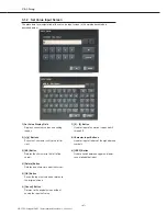
Page 91: ...ft to the left or right 3 BS Button Deletes the character to the left of the cursor 4 Delete Button Deletes one character under the cursor 5 OK Button Saves the input set value and returns to the orig...

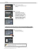
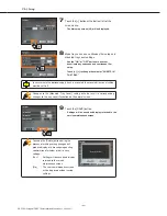
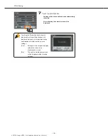
Page 92: ...uch the Maintenance button Since the default log in password setting is ON the user selection screen is displayed 3 Move through the following pages using the scroll button until page 3 3 is displayed...

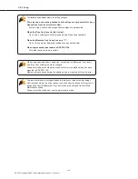
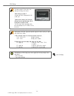
Page 93: ...word Even if the input password is correct if a WEB maintenance user is logged in a message indicating that since a remote user is currently logged in settings cannot be changed 3 3 Switching to the N...

Page 94: ...PACKAGE Tray 1 126 Sets the film package count for each tray Tray 2 126 The value printed on the film box 1 should be set Tray 3 126 This is to allow for the calibration sheet used when film is loaded...

Page 95: ...hanges not possible When unprocessed jobs remain in DRYPRO 793 All setting changes are not possible When an optional additional supply tray is mounted the Mounted Tray Count and Tray Use settings shou...

Page 96: ...yed 4 Set the film size type and count for trays 1 3 Use the and buttons to change displayed values Touching the film count button will produce display of the set value input screen 5 Touch the button...

Page 97: ...be saved and display returned to the service maintenance screen Touching the Return button during the process of making setting changes will produce display of a message requesting confirmation of wh...

Page 98: ...pted 10 supply tray Setting of 10X12 only accepted 8 supply tray Setting of 8X10 only accepted The following two SCU settings must be changed when film setup changes have been made Size of film used T...

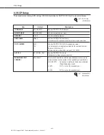
Page 99: ...port number 0 Do not set all values to 0 0 Settings may be made within a range of 100 65000 AE TITLE KC_DPRO3_P001 Sets the DRYPRO 793 AE tile Alphabetical settings are case sensitive EXPANSION PORT...

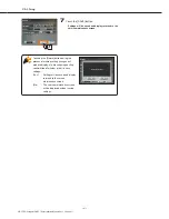
Page 100: ...layed 4 Set the IP address subnet mask gateway and host name Touching each of the buttons will produce display of a set value input screen p 85 Set Value Input Screen 5 Touch the button at the bottom...

Page 101: ...ervice maintenance screen Touching the Return button during the process of making setting changes will produce display of a message requesting confirmation of whether or not to save settings Yes Setti...

Page 102: ...e N EVENT REPORT is not CH03 6000 used Settings may be made within a range of 0 65535 CH04 16 0 AE TITLE CH1 KC_CS1L_U001 Specifies the diagnostic device AE title CH2 KC_PLNK3_U001 A maximum of 16 alp...

Page 103: ...user service maintenance mode active statuses Setting DICOM Communication Print Job DRYPRO 793 Status Displayed Message Registration on External Diagnostic Device STANDARD WARNING FILM EMPTY FAILURE F...

Page 104: ...lm size and type in use set on DRYPRO 793 is used for printing OFF Supply tray selection and printing are carried out in accordance with film information sent by the diagnostic device DEFAULT TRAY CH0...

Page 105: ...channels touch the corresponding device button After inputting new input device information touch the button corresponding to the channel to which the information is to be added 5 Set input device us...

Page 106: ...ill be displayed 9 Make size type check forced specified film use and used film size type settings Use the ON OFF buttons to enable or disable film size type check and forced specified film use settin...

Page 107: ...ton during the process of making setting changes will produce display of a message requesting confirmation of whether or not to save settings Yes Settings will be saved and display returned to the ser...

Page 108: ...om the displayed value 512 512MB print memory mounted 1024 1GB print memory mounted TOTAL OPERATING TIME 0 Displays the total DRYPRO 793 operating time Display only TOTAL PRINTED SHEETS 0 Displays the...

Page 109: ...ystem setup screen 1 2 will be displayed 4 Set the log in password language used and log acquisition mode Use the ON OFF buttons to enable or disable log in password settings Use the buttons to make s...

Page 110: ...booting the normal screen will be displayed Touching the Return button during the process of making setting changes will produce display of a message requesting confirmation of whether or not to save...

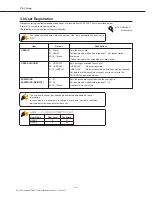
Page 111: ...PASSWORD 01 01 Sets the password requested when the user logs in PASSWORD REINPUT 02 02 Settings may be made within a range of 1 15 03 16 Blank alphanumerical characters 3 8 User Registration Procedur...

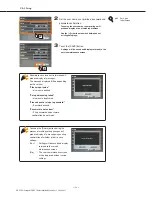
Page 112: ...e displayed Proceed with user information registration amendment deletion 1 Touch the user name button in a blank window The user registration screen will be displayed Display of User Selection Screen...

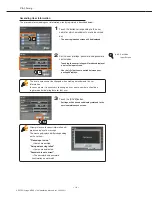
Page 113: ...enance screen will be displayed without saving settings 2 Set the user name user privilege password and password confirmation Touching the user name or user privilege will produce display of a set val...

Page 114: ...ormation In cases where it is necessary to change a user name new data should be registered after deleting data for that user Attempts to save incorrect information will produce display of a message T...

Page 115: ...ng confirmation will be displayed 3 Touch the YES button The user information will be deleted and display returned to the user selection screen Touching No will result in return to the user registrati...

Page 116: ...gs may be made within a range of 10 30 ILLUMINATION CH01 16 2000 Sets the light table brilliance Settings may be made within a range of 0 38000 Since the illumination level is usually sent by the diag...

Page 117: ...his setting determines whether or not film is printed with STAMP MESSAGE CH2 ON a message print count stamp CH03 OFF If set to ON the message may be set from the stamp message CH04 16 ON setting ON Me...

Page 118: ...e is printed in accordance with the specified size Operation when the specified size exceeds the active film size differs depending on the setting made under Behavior INVALID The size specification is...

Page 119: ...but the diagnostic device cannot send a specific size infomation of the requested image Settings may be made within a range of 1 32 P VALUE RECEIVE CH01 16 OFF Sets image gray scale conversion ON or...

Page 120: ...for image processing DICOM The value specified by the diagnostic device is used P CON Maximum minimum density data included in LUT SETUP is used The LUT used is specified from the diagnostic device DI...

Page 121: ...nega posi background density and trim settings Use the buttons to switch between the selection for sorter destination bin film orientation nega posi and background density settings Make the trim setti...

Page 122: ...n setting screen 5 7 will be displayed 12 11 Make stamp stamp message and position settings Pushing the stamp setting button switches between ON and OFF Touching the stamp message display window produ...

Page 123: ...tion of whether or not to save settings Yes Settings will be saved and display returned to the service maintenance screen No The service maintenance screen will be displayed without saving settings 18...

Page 124: ...mmo film using P value DSA_KC_B LUT of our recommendation for blue base film on DSA DSA_LOW_B Blue LUT with slightly lower density setting than DSA_KC_B DSA_HIGH_B LUT with slightly higher density set...

Page 125: ...egistration of LUT data read from the DRYPRO 793 internal library after making fine adjustments 3 Registration of newly created LUT data Displaying the LUT Selection Screen Whichever method of LUT reg...

Page 126: ...registered 5 Touch the RETURN button The LUT setting screen will be displayed 6 Touch the READ button The reference library will be read and displayed at next to the edit LUT number The LUT value disp...

Page 127: ...elect the LUT number to registered by touching the scroll buttons at the left and right of the edit LUT number 2 Registration of LUT data read from the DRYPRO 793 internal library after making fine ad...

Page 128: ...alue buttons touch the desired button 0 16 Touching a LUT value button will produce display of a set value input screen 8 Touch the SAVE button Settings will be saved and display returned to the servi...

Page 129: ...the desired LUT value button 0 16 Touching a LUT value button will produce display of a set value input screen 3 Touch the SAVE button Settings will be saved and display returned to the service mainte...

Page 130: ...YYYY MMM DD Y M D Month expressed alphabetically MMM DD YYYY M D Y Month expressed alphabetically DD MMM YYYY D M Y Month expressed alphabetically TIME FORMAT hh mm Sets the time display format Setti...

Page 131: ...screen 1 2 will be displayed 4 Set the year month day hour and minute Use the buttons to set the year month day hour and minute Changes will be reflected in the current time date display at the botto...

Page 132: ...service maintenance screen Touching the Return button during the process of making setting changes will produce display of a message requesting confirmation of whether or not to save settings YES Sett...

Page 133: ...l Europe Standard Time ON 53 Russian Standard Time ON 17 Central European Standard Time ON 54 SA Eastern Standard Time OFF 18 Central Pacific Standard Time OFF 55 SA Pacific Standard Time OFF 19 Centr...

Page 134: ...ment HPRO unit HPRO cover replacement HPRO unit Cleaning of insertion guide unit with alcohol HPRO unit Opposing roller cleaning pad replacement HPRO unit Cleaning of primary cooling guide with alcoho...

Page 135: ...ns will be displayed 3 Touch the MAINTENANCE SCHEDULE button The maintenance schedule screen will be displayed 4 Touch the MAINTENANCE A button The maintenance schedule A cycle will be displayed 5 Tou...

Page 136: ...eturned to the service maintenance screen Touching the Return button during the process of making setting changes will produce display of a message requesting confirmation of whether or not to save se...

Page 137: ...for test prints TEST PRINT Top bin Output to the top bin Bottom bin Output to the bottom bin SORTER BIN SELECT Bottom bin Sets film destination bin for use when a film jam occurs JAM FILM Top bin Outp...

Page 138: ...screen 1 2 will be displayed 4 Make sorter usage and first bin settings Make sorter usage settings by touching the ON or OFF button Make first bin settings by touching either the 123456 ascending ord...

Page 139: ...service maintenance screen Touching the Return button during the process of making setting changes will produce display of a message requesting confirmation of whether or not to save settings YES Sett...

Page 140: ...Ch 3 Setup 136 DRYPRO Vstage MODEL 793 Installation Manual Ver 1 00 2004 11...

Page 141: ...7 Checking Image Quality This chapter details procedures for checking that images output from DRYPRO 793 comply with standards In cases where the image output does not comply with standards the servic...

Page 142: ...cardboard sheet and light proof bag shown Do not place objects on or lean on the supply tray in extended position Doing so may cause damage 2 Slowly pull the supply tray out to its fully extended posi...

Page 143: ...ting will be shown 5 Take out the new film package from its box and load it into the supply tray with the bar code at the front left Illustration on the film package Animated display of film setting 6...

Page 144: ...ter and firmly close the shutter Do not touch the knob on the shutter Doing so my expose the film 10Take the cutter out of the cutter pocket 11 Cut off the protruding front edge of the package Animate...

Page 145: ...sh after loading film Forgetting to cut off the film package edge before inserting the film into the supply tray and locking the supply tray will result in the Film Setting button being displayed agai...

Page 146: ...adjustments after installation In cases where the internal densitometer is not to be calibrated using the facility densitometer only a density linearity check is necessary Installation engineers must...

Page 147: ...ect the combination numbers shown above If there are changes in the combination numbers internal densitometer calibration should be re executed according to the chart above The densitometer used shoul...

Page 148: ...on screen will be displayed 3 Select the tray in which the film type to be calibrated is loaded 4 After touching the Print button touch Yes on the confirmation screen to print the calibration sheet Th...

Page 149: ...density value selection screen will be displayed 4 Touch the DENSITOMETER CORRECT button The tray selection print screen will be displayed 5 Select the supply tray used for calibration in step 1 and t...

Page 150: ...be displayed 2 Input the density values measured in step 3 3 Touch the SAVE button after completion of input 4 Touch the NEXT button The calibration pattern screen will be displayed 5 Touch the PRINT...

Page 151: ...used values in the Mammography column should be compared If results satisfy the following three conditions density calibration results may be judged to be normal A The difference between all internal...

Page 152: ...sure that film is loaded in each tray For details of he procedure for loading film refer to the operation manual 2 Print out two flat patterns from supply tray 1 1 Touch the menu to invoke the menu mo...

Page 153: ...e The display will return to the service maintenance mode screen 6 Touch the TEST PRINT button under the PRINT item again The test print selection screen will be displayed 7 Touch the FLAT button The...

Page 154: ...the input device Selection of NO SELECT here will result in the automatic settings shown below in accordance with the film type selected in step 6 LUT setting Linear Blue film Maximum density 300 Mini...

Page 155: ...kewise print out one SMPTE pattern from supply tray 3 if installed 7 Touch the RETURN button Display will return to the normal screen The SMPTE pattern film will be printed 7 In cases where print cond...

Page 156: ...07 08 09 10 11 12 13 14 15 16 01 02 03 04 05 06 07 08 09 10 11 12 13 14 15 16 01 02 03 04 05 06 07 08 09 10 11 12 13 14 15 16 01 02 03 04 05 06 07 08 09 10 11 12 13 14 15 16 01 02 03 04 05 06 07 08 0...

Page 157: ...5 16 01 02 03 04 05 06 07 08 09 10 11 12 13 14 15 16 100 90 80 70 60 50 50 40 30 20 10 0 2 For Film Sizes 10X12 8X10 1 Check to ensure that the densitometer to be used is adjusted to zero 4 In cases w...

Page 158: ...m Setting Max Density Min Density Blue 300 20 Point Min Value Standard Value Max Value 1 15 20 25 2 34 39 44 3 52 57 62 4 71 76 81 5 90 95 100 6 108 113 118 7 127 132 137 8 146 151 156 9 164 169 174 1...

Page 159: ...nsity Blue 300 20 Film Setting Max Density Min Density Mammography 400 20 Point Min Value Standard Value Max Value 100 15 20 25 90 43 48 53 80 71 76 81 70 99 104 109 60 127 132 137 50 155 160 165 40 1...

Page 160: ...pattern 1 Invoke the menu mode by touching the menu key 2 log into the service maintenance mode using service privilege 3 Touch the TEST PRINT button under the PRINT item The test print selection scre...

Page 161: ...AME can be correctly seen and use a ruler to measure the length of the unexposed margins at the left and right edges of the frame pattern No adjustments to the write start writing position are necessa...

Page 162: ...horter than the right increase the value shown on the HD Offset button for the corresponding film size by the difference The image data writing position will be adjusted accordingly 4 Touch the SAVE b...

Page 163: ...n 2 6 will be displayed 3 4 5 4 4 3 Making Adjustments of Write Start Position in the Sub Scan Direction Vertical The procedure for making adjustments in the sub scan direction is described below 1 Tu...

Page 164: ...e write start position will be adjusted accordingly 4 Touch the SAVE button Display will return to the service maintenance mode menu screen 5 Repeat print out of the frame pattern and measurement of t...

Page 165: ...from and Backup of Setup Data Finally a print job should b sent from an external device to DRYPRO 793 and a check carried out to ensure that printing is successfully executed After carrying out the ab...

Page 166: ...hub with auto negotiation capabilities as a 110BASE TX hub is recommended The facility network administrator should be consulted for details If using 100BASE T CAT5 or CAT6 LAN cable should be used 2...

Page 167: ...ther setting items will be displayed 3 Touch the DATA BACKUP button The data backup screen will be displayed 4 Touch the BACKUP button p 86 Switching to the Service Maintenance Mode Backup data can be...

Page 168: ...version 5 5 or higher The message page cannot be displayed will appear 4 Input the DRYPRO IP address after http in the Address textbox Input should be in the following format http IP Address The Web m...

Page 169: ...icon will be displayed 7 Click SERVICE in the User ID box and input the service privilege password in the Password box The input password will be displayed as a series of asterisks or dots in place of...

Page 170: ..._xxxxxxxxxx tgz xxxxxxxxxx shows the time and date in a 10 digit format will be automatically allocated the file The top page is displayed after data has been saved 11 Click the Save button Backup wil...

Page 171: ...2004 11 Web Maintenance Mode While procedures for making settings using DRYPRO 793 were described in Chapter 3 Setup settings may also be made from the maintenance PC This chapter deals with procedure...

Page 172: ...web maintenance modes may be used simultaneously on the network Like the maintenance mode from the DRYPRO 793 printing and receipt of print data from diagnostic devices is not possible while the Web m...

Page 173: ...r http in the Address textbox The Web maintenance tool menu mode screen will be displayed 4 Connect the other end of the Ethernet cable connected in step 2 to the hub to which the DRYPRO 793 Ethernet...

Page 174: ...lick SERVICE The pull down menu will be closed and SERVICE displayed in the user ID window 10Input the service password from the PC keyboard The input password will be shown as a series of asterisks o...

Page 175: ...he procedure for terminating the Web maintenance mode maintenance mode is described below 1 1 Click the Log out button at the top left of the screen aconfirmation screen will be displayed 2 Click the...

Page 176: ...he film type for film loaded in each tray Tray 2 B B Blue base film Tray 3 M C Clear base film M Mammography film COUNT Tray 1 0 Sets the film count for film loaded in each tray Tray 2 0 Settings may...

Page 177: ...ngs are not possible When the Tray Use is set to Not in Use Tray 2 and 3 settings are not displayed setting changes not possible When the Mounted Tray Count is set to 1 Tray 3 setting are not displaye...

Page 178: ...A maximum of 16 alphanumerical characters may be specified PORT NUMBER 6000 Sets the DRYPRO 793 DICOM receipt port number 104 It is not necessary to duplicate settings for the same port number 0 Do n...

Page 179: ...200 0 0 0 0 should be specified in cases where N EVENT REPORT is CH03 192 168 20 90 not used CH04 16 0 0 0 0 HOST NAME CH01 16 Blank Sets the host name of the diagnostic device This should be left bl...

Page 180: ...including when the film is empty Setting DICOM Communication Print Job DRYPRO 793 Status Displayed Message Registration on External Diagnostic Device STANDARD FAILURE CHECK PRINTER FAILURE FAILURE CHE...

Page 181: ...ored and film size and type information settings in DRYPRO 793 used for printing OFF Supply tray selection and printing are carried out in accordance with film information sent by the diagnostic devic...

Page 182: ...cted under BORDER SIZE in the print condition setup is described below Item Default Descriptions TOP BOTTOM SIZE Sets the upper lower border size Settings may be made in units of 0 1mm LEFT RIGHT SIZE...

Page 183: ...the following languages ENGLISH GERMAN FRENCH SPANISH ITALIAN PORTUGUESE SCANDINAVIA JAPANESE CHINESE LOG WRITE MODE NORMAL Sets the log output status NORMAL Normal mode DETAILS Detailed mode Unless o...

Page 184: ...intenance Mode 180 DRYPRO Vstage MODEL 793 Installation Manual Ver 1 00 2004 11 In cases where the optional memory expansion is installed check that 1024 is shown in the display No setting changes are...

Page 185: ...will result in addition of the information in the line indicated by a yellow arrow mark MODIFY Button Allows modification of registered user information The screen below is displayed below the menu di...

Page 186: ...he user name 02 User02 Settings may be made within a range of 1 32 alphanumerical characters 03 16 Blank Cannot be input when amending user information PASSWORD 01 01 Sets the password requested when...

Page 187: ...ribed below The following print conditions may be set Item Default Descriptions LUT SELECT CH01 16 1 Sets the LUT number to be used Settings may be made within a range of 1 7 For details of making LUT...

Page 188: ...umination level is usually sent by the diagnostic device changes to this setting are not necessary FLIP CH01 16 OFF Sets image flip ON The image is printed flipped OFF The image is printed without bei...

Page 189: ...CH01 16 1 Sets the enlargement ratio valid when smoothing is set 7 RATIO Used for example when the user wishes to specify print dimensions but the diagnostic device cannot send image size requests Set...

Page 190: ...sing DICOM The value specified by the diagnostic device is used P CON Maximum minimum density data included in LUT settings is used The LUT used is specified from the diagnostic device DICOM PRIORITY...

Page 191: ...OFF If set to ON the message may be set from the stamp message CH04 16 ON setting ON Message print count is printed OFF Message print count is not printed STAMP SETUP CH1 OFF This setting determines...

Page 192: ...DECISION button U D R L Button Shifts the LUT curve U button Shifts the LUT curve upward D button Shifts the LUT curve downward R button Shifts the LUT curve to the right L button Shifts the LUT curv...

Page 193: ...on Click the CANCEL button to return to the LUT Setup screen OK Button Saves the current LUT curve setting ORIGINAL Button Displays the previous LUT value image in the left image field MODIFY Button D...

Page 194: ...expressed as a numerical value MM DD YYYY M D Y Month expressed as a numerical value DD MM YYYY D M Y Month expressed as a numerical value YYYY MMM DD Y M D Month expressed alphabetically MMM DD YYYY...

Page 195: ...acific Standard Time OFF 55 SA Pacific Standard Time OFF 19 Central Standard Time ON 56 SA Western Standard Time OFF 20 China Standard Time OFF 57 Samoa StandardTime OFF 21 Dateline Standard Time OFF...

Page 196: ...ng the deodorant filter case cooling conveyor unit Cleaning sheet cleaning descent transport unit Cleaning of suction pads with alcohol supply unit Densitometer cleaning cooling conveyor unit Overall...

Page 197: ...ELECT Bottom bin Sets the destination bin for test prints TEST PRINT Top bin Output to the top bin Bottom bin Output to the bottom bin SORTER BIN SELECT Bottom bin Sets film destination bin for use wh...

Page 198: ...Ch 6 Web Maintenance Mode 194 DRYPRO Vstage MODEL 793 Installation Manual Ver 1 00 2004 11...

Page 199: ...DRYPRO Vstage MODEL 793 Installation Manual Ver 1 00 2004 11 195 Specifications Specifications of the DRYPRO 793 is detailed in the following pages...

Page 200: ...4 5A 50 60Hz UL 120V 10 AC single phase 9 0A 60Hz approx 1200kJ hr approx 286kcal hr 15 30 30 70 RH no condensation 20 60 20 90 RH no condensation Standby 50 dB or less Printing 55 dB or less Color L...

Page 201: ...Deodorant Filter Attached document for doctors Inspection sheet Protection hardware red parts recycle bag Clamp 2 pcs Suction cups 2pcs Film Holder 2pcs Lis 793 6CH Sorter Multi Client Software Licens...

Page 202: ...oile B P 50077 95948 ROISSY C D G CEDEX FRANCE TEL 1 4938 6550 KONICA CANADA INC 1329 Meyerside Drive Mississauga Ontario L5T 1C9 CANADA TEL 905 670 7722 Konica Minolta Photo Imaging UK Ltd Plane Tree...

Reviews: