6
381298/C
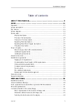
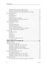
Connecting the USB cable between the Operating Panel and the Processor
Connecting the dual cable between the Operating Panel and the Processor
Connecting ground to the Operating Panel ..........................................................147
Connecting external devices to the Processor Unit using serial interfaces ...........148
Connecting external devices to the Processor Unit using Ethernet
Connecting the Ethernet cable from the Transceiver Unit to the Processor
Connecting the transducer to the Transceiver Unit ..............................................152
Processor Unit graphic adapter ......................................................................................152
Moxa CP114EL-I Serial line adapter.............................................................................155
Moxa CP114EL-I overview..................................................................................155
Moxa CP114EL-I connectors ...............................................................................156
Setting up the Moxa CP114EL-I serial ports in Windows 7 ................................157
AC mains power cable using IEC C13 inline socket ...........................................160
Grounding cable ...................................................................................................161
Communication and power cable for the Operating Panel...................................162
RS-232 serial line connection using three wires ..................................................163
RS-232 serial line connection using five wires ....................................................164
RS-422 serial line connection using five wires ....................................................165
RS-232 used as synchronization trigger (input or output) ...................................166
Moxa CP114EL-I Serial line adapter ...................................................................167
RJ45 High speed Ethernet cable (1000Base-t).....................................................169
Cable trays ............................................................................................................170
Radio frequency interference ...............................................................................171
Physical protection of cables ................................................................................171
Grounding of system cables .................................................................................172
Cable connections and terminations.....................................................................172
Cable identification...............................................................................................172
Cable glands and termination procedures ............................................................173
SETTING TO WORK .............................................................. 178
Setting to work summary ...............................................................................................179
Verifying that the SN90 is ready for operational use.....................................................181
Verifying that operational power is correct ..........................................................181
Verifying that all cables are properly connected ..................................................182
Visual inspection of the display............................................................................183
Visual inspection of the Processor Unit ...............................................................184
Simrad SN90
Summary of Contents for Simrad SN90
Page 2: ......
Page 117: ...381298 C 115 Related topics Installation summary page 65 Installing the transducer ...
Page 236: ...234 381298 C 372915 Clamping frame Simrad SN90 ...
Page 295: ......
Page 296: ... 2016Kongsberg Maritime ISBN 978 82 8066 179 1 ...
Page 297: ......


