198
381298/C
3
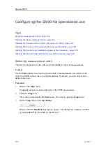
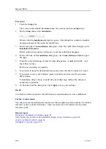
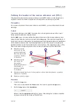
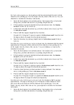
On the left side of the
Installation
dialog box, click the small white triangle next to
Installation Parameters
.
Observe that a menu opens with access to all the individual sub-pages.
4
On the left side of the
Installation
dialog box, click
MRU
to open the page.
5
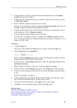
From the vessel drawings, extract the relevant offset information, and insert those
values.
Do this as accurately as possible.
6
From the information provided by the personnel installing the motion sensor, extract
the relevant rotation information, and insert those values.
7
At the bottom of the dialog box, click
Apply
to save your settings.
Related topics
Transducer installation principles, page 67
Determining the location and installation angles of the transducer, page 88
Vessel coordinate system, page 61
Installation remarks, page 216
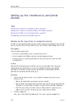
Defining the location of the global positioning system (GPS)
The physical location of the global positioning system (GPS) antenna relative to the
transducer is required to allow the SN90 to show the correct navigational information in
the SN90 presentation.
Prerequisites
For accurate location of the global positioning system (GPS) antenna, you need the
detailed vessel drawings.
Context
The global positioning system (GPS) measures the geographical location of the vessel.
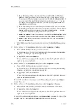
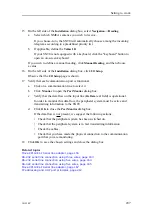
On the
GPS
page, you must define the physical location of the GPS antenna related
to the
Ship Origin
.
Procedure
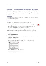
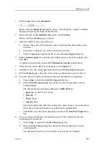
1
Click the
Setup
icon.
The icon is located under the
Main
menu. It is used to open the
Setup
menu.
2
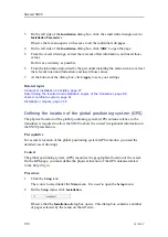
On the
Setup
menu, click
Installation
.
Observe that the
Installation
dialog box opens. This dialog box contains a number
of pages selected by the menu on the left side.
Simrad SN90
Summary of Contents for Simrad SN90
Page 2: ......
Page 117: ...381298 C 115 Related topics Installation summary page 65 Installing the transducer ...
Page 236: ...234 381298 C 372915 Clamping frame Simrad SN90 ...
Page 295: ......
Page 296: ... 2016Kongsberg Maritime ISBN 978 82 8066 179 1 ...
Page 297: ......

