192
381298/C
Context
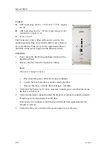
A
LEDs indicating that the +5 Vdc and +12 Vdc supplies
are ok
B
LED indicating that the +72 Vdc (high voltage for the
transmitters) supply is ok
C
Service switch
The Transceiver Unit is fitted with a service switch. For
normal operation, this service switch shall be set to
Remote
.
To verify that the Transceiver Unit is operational, observe
the LEDs on the power supply and the Ethernet switch.
Procedure
1
Power down the SN90 using the
Power
button on the
Operating Panel.
2
Remove the door from the transceiver cabinet.
Note
The heat exchanger is heavy.
a
Disconnect the power cable for the heat exchanger.
b
Loosen the four bolts that are used to secure the door.
c
Remove the door - with the heat exchanger - carefully.
3
Verify that the Transceiver Unit is connected to mains power, and that the circuit
breaker is switched on.
4
Verify that the power connector under the transceiver cabinet is properly inserted.
If mains power is disconnected, rectify this.
When power is reconnected, the Ethernet switch will need approximately two
minutes to start up.
5
Verify that the service switch on the power supply is set to
Remote
.
Simrad SN90
Summary of Contents for Simrad SN90
Page 2: ......
Page 117: ...381298 C 115 Related topics Installation summary page 65 Installing the transducer ...
Page 236: ...234 381298 C 372915 Clamping frame Simrad SN90 ...
Page 295: ......
Page 296: ... 2016Kongsberg Maritime ISBN 978 82 8066 179 1 ...
Page 297: ......

