78
381298/C
Note
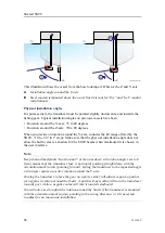
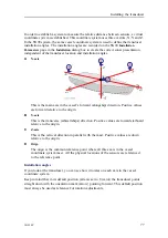
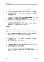
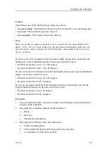
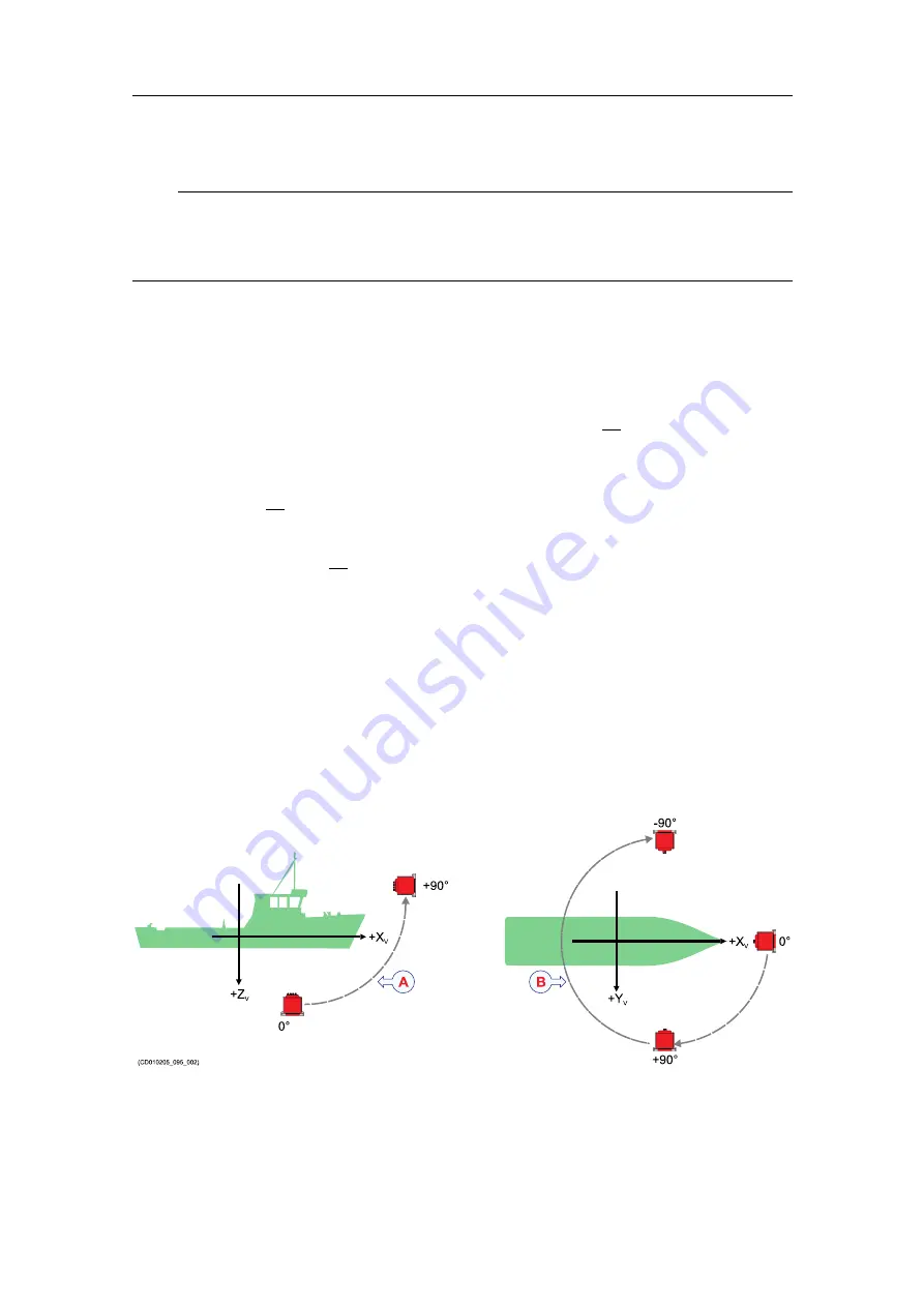
In order to establish the correct installation angles, you must do a virtual exercise. It
is very important that you define the three values in the correct order: first X, then Y
and finally Z.
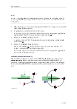
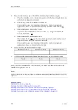
1
Place the transducer in its virtual start position with the face straight down, and with
the 0–mark pointing forward.
2
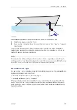
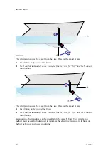
If necessary, rotate the transducer on the X-axis.
If you wish to point your transducer forward for trawl or navigational applications,
the value for X shall be 0 (zero), and the 0–mark must be up.
3
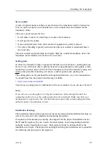
Rotate the transducer along the Y-axis.
A positive value will "tilt" the transducer face up. Keep in mind that the 0–mark
shall still be up.
4
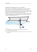
Rotate the transducer along the Z-axis.
The 0–mark shall be up, and the value for Z (positive towards starboard and
negative towards port) will define the direction.
If you wish to point your transducer forward for trawl or navigational applications,
the value for Z shall be 0 (zero).
Changing the installation angles
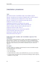
The installation angles are recorded on the SN90
Installation Parameters
page in the
Installation
dialog box to create the correct sonar presentation independent of the
transducer location and installation angles. This must be done once the transducer has
been installed, and the SN90 has been started. You will normally only need to do this
once.
+90°
0°
+90°
-90°
0°
(CD010205_095_002)
+Z
V
+Y
V
+X
V
+X
V
Simrad SN90
Summary of Contents for Simrad SN90
Page 2: ......
Page 117: ...381298 C 115 Related topics Installation summary page 65 Installing the transducer ...
Page 236: ...234 381298 C 372915 Clamping frame Simrad SN90 ...
Page 295: ......
Page 296: ... 2016Kongsberg Maritime ISBN 978 82 8066 179 1 ...
Page 297: ......

