124
381298/C
Context
Free bulkhead space is required to mount the
Transceiver Unit.
Observe the limitations due to the cable lengths. The
distance between the transducer and the Transceiver
Unit is restricted by the length of the transducer cables.
The distance from a power outlet is restricted by the
length of the power cables. If required, you may need
to move the power outlet, or replace the power cables
with longer types.
The Transceiver Unit is heavy. Make sure that
the necessary manpower and lifting equipment are
available before you start the installation work.
The Transceiver Unit must be mounted as a complete unit. The door must not be opened
until the unit is securely fastened to the bulkhead.
Procedure
1
Prepare the location and the necessary tools.
2
Observe the installation requirements.
• The Transceiver Unit must be mounted to the bulkhead.
• The position must be chosen to fit the available cable lengths between the
Transceiver Unit and the other units it connects to.
• Provide ample space around the cabinet to allow for inspection, maintenance
and parts replacement.
• Make sure that the space allows the cabinet door to be fully dismounted for
unobstructed access to its internal parts.
• Verify that the installation does not cause problems with existing cabling,
ventilation ducts, piping etc. Check both sides of the bulkhead.
• Make sure that enough space is made available for maintenance purposes.
• Make sure that adequate ventilation is available to avoid overheating.
• Ensure that the installation method allows for the physical vibration, movements
and forces normally experienced on a vessel.
3
Verify that the chosen location meets the requirements.
4
Remove the two mounting brackets which are fastened to the shock absorbers
on the Transceiver Unit.
An Allen key is provided for this purpose. It is located in the plastic bag fastened to
the upper shock absorber.
5
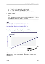
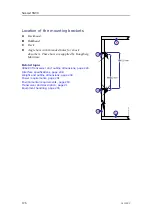
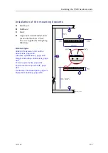
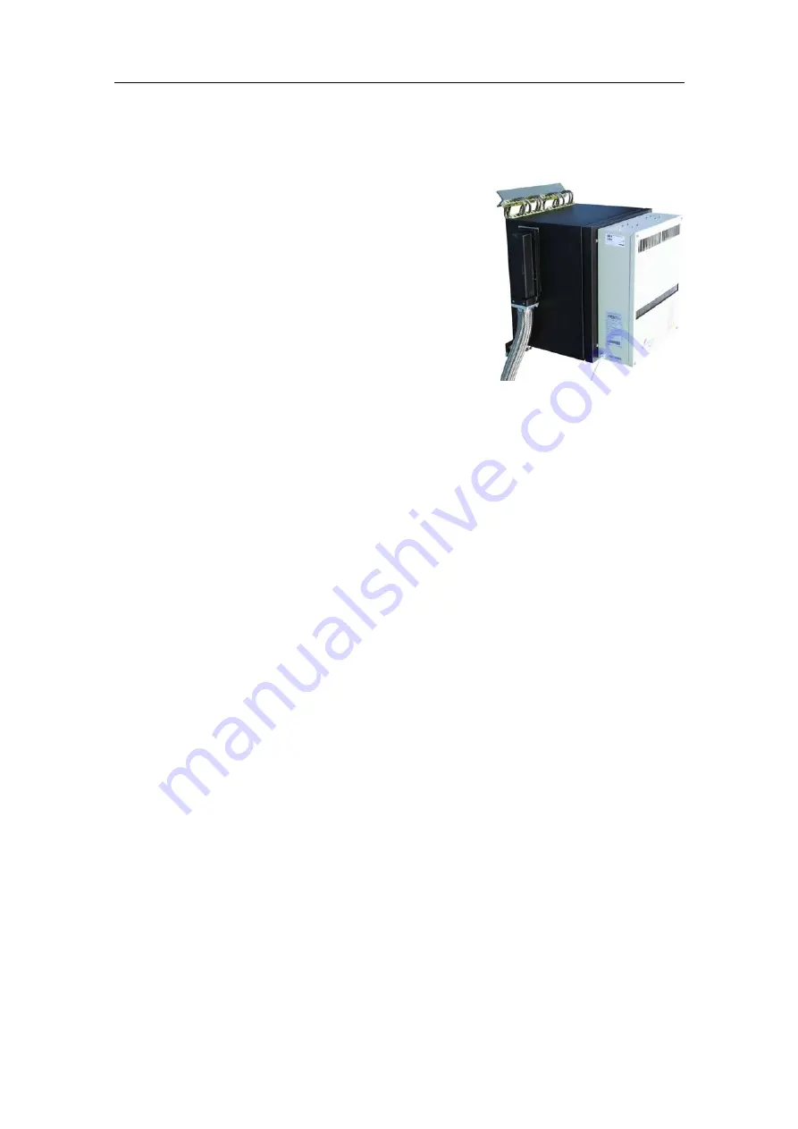
Weld the mounting brackets securely to the bulkhead as shown in the illustrations.
6
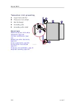
Use a chain fall or similar device to lift the Transceiver Unit into position.
Simrad SN90
Summary of Contents for Simrad SN90
Page 2: ......
Page 117: ...381298 C 115 Related topics Installation summary page 65 Installing the transducer ...
Page 236: ...234 381298 C 372915 Clamping frame Simrad SN90 ...
Page 295: ......
Page 296: ... 2016Kongsberg Maritime ISBN 978 82 8066 179 1 ...
Page 297: ......

