REMARK
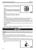
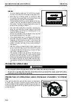
• Turn the starting switch key (1) to OFF (A) position,
and the control box also shuts down at the same time.
• When the key in starting switch (1) is turned to OFF
(A) position, the engine stops, but the machine's main
power supply is not turned off immediately.
This is because that the power is supplied for the con-
troller to save the operating condition and then finish
the system. The time to keep supplying the power de-
pends on the operating condition.
• Also when the cooling fan is used for a cleaning pur-
pose, the machine's main power supply is not turned
off immediately, even if the key in starting switch (1) is
turned to OFF (A) position.
This is for protection of the hydraulic circuit, and the
power is kept supplied for 7 seconds.
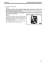
• If the starting switch key (1) is turned to OFF (A) posi-
tion while the engine is still hot, guidance (2) may be
displayed on the machine monitor. To cool down the
engine before stopping, run it at low idle for approxi-
mately 5 minutes, because it may cause damage to
the devices.
• After the engine is stopped, DEF in DEF injector and
pump is automatically purged and returned to the tank
to prevent malfunction of the devices caused by freez-
ing of DEF or deposition of urea.
The devices continue the operation for several mi-
nutes for this reason after the engine starting switch
key is turned to OFF position, but this is not abnormal.
Do not turn the battery disconnect switch to OFF posi-
tion while the devices are purging DEF. After the purg-
ing operation is finished, the devices stop automatical-
ly.
PROHIBITED OPERATIONS
k
k
WARNING
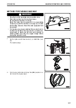
• Do not operate the work equipment control lever when the machine is traveling.
• If any lever is operated when the auto-deceleration is being actuated, the engine speed will sudden-
ly increase, so be careful when operating.
PROHIBITION OF OPERATIONS USING HYDRAULIC CYLINDERS TO STROKE
END
If the work equipment is used with the cylinder rod operated to
its stroke end, and given impact by some external force, the
sensors installed to the hydraulic cylinders may be broken. Do
not perform operations with the hydraulic cylinder fully retracted
or fully extended.
MACHINE OPERATIONS AND CONTROLS
OPERATION
3-56
Summary of Contents for A31001
Page 12: ...LOCATION OF SAFETY LABELS Options are shown with marks in the figure SAFETY LABELS SAFETY 2 4...
Page 106: ......
Page 107: ...SPECIFICATIONS 5 1...
Page 110: ......
Page 116: ......
Page 117: ...SETTING 7 1...
Page 311: ...EXECUTIONS 8 1...
Page 376: ...PC360LCi 11 PC390LCi 11 HYDRAULIC EXCAVATOR Form No CEAM032703...

