REMARK
If adjustment is not enough with this position adjustment of
control box, slide the whole seat, and perform the position
adjustment of R.H. work equipment control lever. For the
adjustment method, see “METHOD FOR ADJUSTING OP-
ERATOR'S SEAT”.
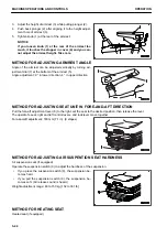
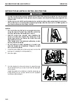
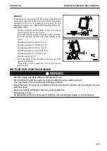
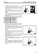
• Fix the control box at the position shown in the figure
on the right for you to see it better.
This is an optimum position because it does not inter-
fere with machine monitor, and front visibility is se-
cured.
Mounting position (b): 40 mm {1.6 in}
Mounting position (c): 55 mm {2.2 in}
Mounting position (d): 51 mm {2.0 in}
Mounting position (e): 168 mm {6.6 in}
Mounting position (f): 78 mm {3.1 in}
Mounting angle (g): 79 °
• Fix it according to the mounting procedure, and this
position is obtained.
This position is just a guide line. You do not need to
follow exactly.
METHOD FOR STARTING ENGINE
k
k
WARNING
• Start the engine only while sitting on the operator's seat.
• Do not attempt to start the engine by short-circuiting the engine starting circuit.
This may cause a fire or serious personal injury or death.
• Check that there is no person or obstacle in the area around the machine, then sound the horn and
start the engine.
• Never use starting aid fluids as they may cause explosions.
• Exhaust gas is toxic.
Be particularly careful to ensure good ventilation when starting the engine in confined spaces.
OPERATION
MACHINE OPERATIONS AND CONTROLS
3-47
Summary of Contents for A31001
Page 12: ...LOCATION OF SAFETY LABELS Options are shown with marks in the figure SAFETY LABELS SAFETY 2 4...
Page 106: ......
Page 107: ...SPECIFICATIONS 5 1...
Page 110: ......
Page 116: ......
Page 117: ...SETTING 7 1...
Page 311: ...EXECUTIONS 8 1...
Page 376: ...PC360LCi 11 PC390LCi 11 HYDRAULIC EXCAVATOR Form No CEAM032703...


