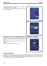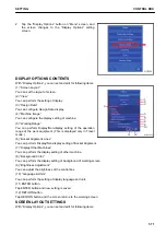
2.
The width of the Grade Indicator to be displayed in green
can be set by the inputted value.
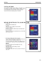
METHOD FOR SETTING LEFT GRADE INDICATOR
Tap “Left Indicator” column and input the numeric value.
After completing the input, tap “OK” button.
Tap ENTER button to save the setting.
You can offset the detection position of the bucket edge from
the left to right.
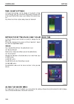
METHOD FOR SETTING RIGHT GRADE INDICATOR
Tap “Right Indicator” column, and input the numeric value.
After completing the input, tap “OK” button.
Tap ENTER button to save the setting.
You can offset the detection position of bucket edge from the
right to left.
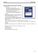
MEASUREMENT DISTANCE
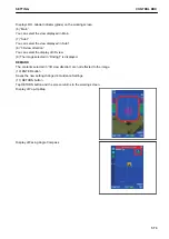
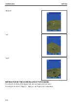
You can set the measurement method of the distance between the bucket edge and Surface.
SETTING
CONTROL BOX
7-61
Summary of Contents for A31001
Page 12: ...LOCATION OF SAFETY LABELS Options are shown with marks in the figure SAFETY LABELS SAFETY 2 4...
Page 106: ......
Page 107: ...SPECIFICATIONS 5 1...
Page 110: ......
Page 116: ......
Page 117: ...SETTING 7 1...
Page 311: ...EXECUTIONS 8 1...
Page 376: ...PC360LCi 11 PC390LCi 11 HYDRAULIC EXCAVATOR Form No CEAM032703...


