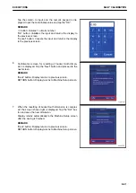
5.
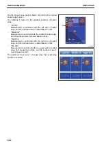
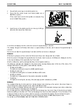
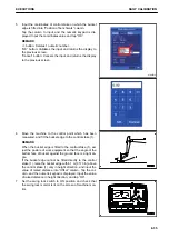
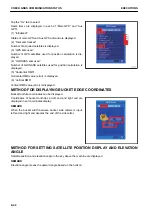
Input the coordinates of control stake on which the bucket
edge is fitted into “Position of benchmark” column.
Tap the column to input, and the numeric keypad is dis-
played. Input the coordinates value and tap “OK”.
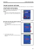
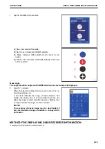
REMARK
<< button: Deletes 1 numeric number.
“OK” button: Validates the input and returns the display to
the previous screen.
“Cancel” button: Cancels the input and returns the display
to the previous screen.
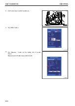
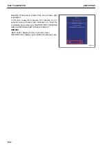
6.
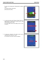
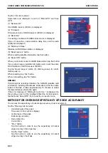
Move the machine to the control point which has been
measured, and fit the bucket edge to the control stake (1).
REMARK
When the bucket edge is fitted to the control stake (1), ad-
just the posture of work equipment so that the angle of the
bottom face of bucket against the ground face is a right an-
gle.
If the bucket edge cannot be fitted directly to the control
stake (1), raise the bucket edge within 1 m {3 ft 3 in} above
the control stake (1) only in height direction, and input the
value of raised distance into “Offset” column. Tap the col-
umn, and the numeric keypad is displayed. Input the value
of raised distance in height direction, and tap “OK”.
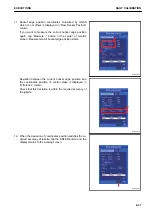
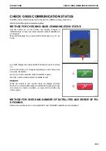
7.
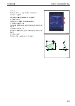
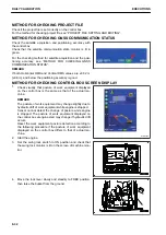
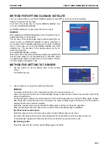
Set the swing lock switch to ON position and check that
the swing lock monitor is lit on the screen of machine mon-
itor.
AJD03515
EXECUTIONS
DAILY CALIBRATION
8-35
Summary of Contents for A31001
Page 12: ...LOCATION OF SAFETY LABELS Options are shown with marks in the figure SAFETY LABELS SAFETY 2 4...
Page 106: ......
Page 107: ...SPECIFICATIONS 5 1...
Page 110: ......
Page 116: ......
Page 117: ...SETTING 7 1...
Page 311: ...EXECUTIONS 8 1...
Page 376: ...PC360LCi 11 PC390LCi 11 HYDRAULIC EXCAVATOR Form No CEAM032703...


