5.
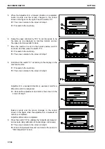
When the Adjustment in a forward direction is completed,
buzzer sounds, and the screen changes to the screen
shown in the figure on the right. Press the switch “F3”.
F2: The screen returns to the screen of step 2.
F3: Proceeds to the next step.
6.
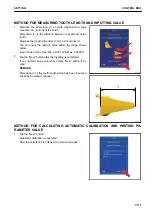
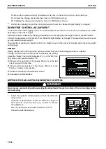
Swing the upper structure by 180 ° to set its posture to be
the same as one displayed on machine monitor, and set
the upper structure parallel to track.
7.
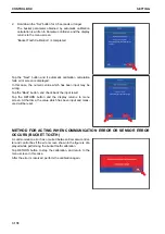
Move the machine to set it to the correct posture, wait 10
seconds, and then press the switch “F3”.
F3: Proceeds to the next step.
F5: The screen returns to the screen of step 2.
8.
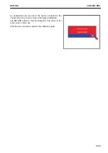
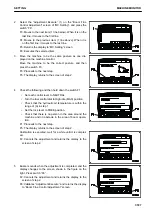
Hold down the switch “F1” according to the display on the
machine monitor.
F1: Proceeds to the next step.
F5: The screen returns to the screen of step 5.
Adjustment in a rearward direction is executed, wait for a
little while until it is completed.
F2: Cancels the adjustment and returns the screen to the
screen of step 5.
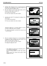
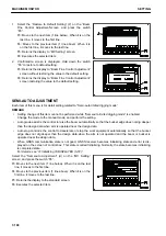
Buzzer sounds and the screen changes to the screen
shown in the figure when the adjustment in a rearward di-
rection is completed.
Adjustment Execute is completed.
9.
Press the switch “F6” to validate the “Adjustment Execute”,
and execute daily calibration of bucket edge continuously.
F2: The screen returns to the screen of step 5.
F6: Enters “Adjustment Execute” and returns the screen to
“IMU Adjustment” screen.
MACHINE MONITOR
SETTING
7-184
Summary of Contents for A31001
Page 12: ...LOCATION OF SAFETY LABELS Options are shown with marks in the figure SAFETY LABELS SAFETY 2 4...
Page 106: ......
Page 107: ...SPECIFICATIONS 5 1...
Page 110: ......
Page 116: ......
Page 117: ...SETTING 7 1...
Page 311: ...EXECUTIONS 8 1...
Page 376: ...PC360LCi 11 PC390LCi 11 HYDRAULIC EXCAVATOR Form No CEAM032703...


