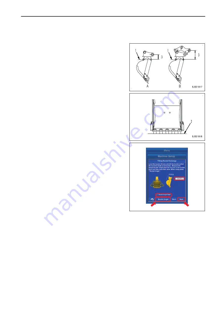
METHOD FOR MEASURING BUCKET FOOT ANGLE AND TILT WIDTH ANGLE
(TILT BUCKET)
1.
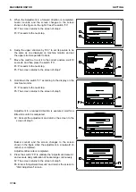
Set the tilt axis (1) to be horizontal by using a level or a la-
ser level.
2.
With that condition, set the bucket tooth tip (2) to be hori-
zontal.
(A): When the quick coupler is not installed
(B): When the quick coupler is installed
3.
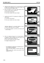
Tap the “Bucket Angle” button.
A tick is put in the check box of “Bucket Angle Read”, and
work equipment angle at that posture is saved.
4.
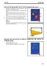
Measure the vertical distance (3) between the bucket foot
pin and the tilt axis by using a tape measure and a plumb
or a laser level, and input the numeric value.
Measure the length dimension to mm unit.
You can input the numeric value within the range shown
below.
Input range of numeric value Min: 0.0001 m to Max:
5.9999 m
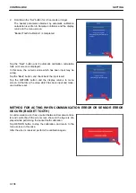
5.
Tap the “Next” button after the inputting is completed.
If any numeric value column is empty, “Next” button is in-
valid.
SETTING
CONTROL BOX
7-171
Summary of Contents for A31001
Page 12: ...LOCATION OF SAFETY LABELS Options are shown with marks in the figure SAFETY LABELS SAFETY 2 4...
Page 106: ......
Page 107: ...SPECIFICATIONS 5 1...
Page 110: ......
Page 116: ......
Page 117: ...SETTING 7 1...
Page 311: ...EXECUTIONS 8 1...
Page 376: ...PC360LCi 11 PC390LCi 11 HYDRAULIC EXCAVATOR Form No CEAM032703...


