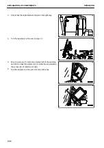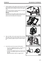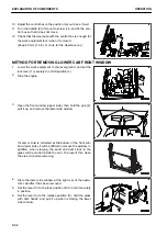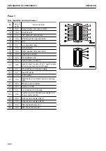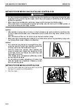
METHOD FOR INSTALLING CONTROL BOX
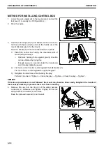
1.
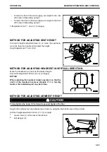
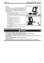
Lower the work equipment to the level ground, and set the
lock lever (1) securely to LOCK position (L).
2.
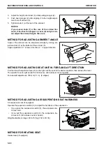
Stop the engine.
3.
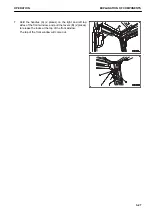
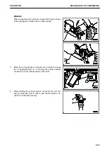
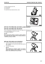
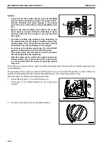
Hold the cab fixing ball (C) and ball (D) at the rear of con-
trol box with the mount (B), and turn the handle (A) of the
mount (B) clockwise to fix the mount.
Face the handle (A) of the mount downward to operate.
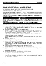
1) Install the control box having the clearance (slit) of
mount facing sideways.
• Optimum holding force against gravity direction
can be obtained by doing this.
• Enough space is secured under the handle (A)
and it makes tightening easier.
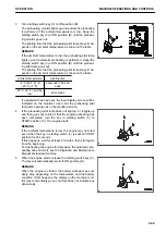
2) Fix the mount so that it is vertical against the ball bracket (C).
Fix it so that it is vertical against the right side glass.
3) Retighten it a few times while checking the play.
Perform it in order of “Tighten → Check the play → Tighten → Check the play → Tighten ”.
REMARK
If the above procedures are not followed, the mount may become loose easily. Retighten the handle of
the mount periodically. It prevents the mount from loosening.
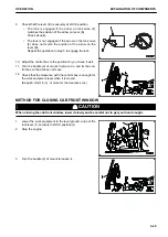
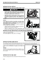
4.
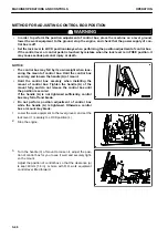
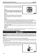
Remove the cap, turn the ring (4) of the wiring harness
connector (2) clockwise, and tighten it lightly so that the
wiring harness connector (2) can move.
Keep the removed cap and do not loose it.
EXPLANATION OF COMPONENTS
OPERATION
3-38
Summary of Contents for A31001
Page 12: ...LOCATION OF SAFETY LABELS Options are shown with marks in the figure SAFETY LABELS SAFETY 2 4...
Page 106: ......
Page 107: ...SPECIFICATIONS 5 1...
Page 110: ......
Page 116: ......
Page 117: ...SETTING 7 1...
Page 311: ...EXECUTIONS 8 1...
Page 376: ...PC360LCi 11 PC390LCi 11 HYDRAULIC EXCAVATOR Form No CEAM032703...

