intelligent Machine Control SYSTEM
CONTROL BOX
k
k
WARNING
• Do not operate the control box during the operation of the work equipment in order to prevent unex-
pected accident from occurring. Also, do not gaze the control box during performing the work.
• The image of the machine displayed on the control box is only a representation. The image dis-
played on the control box is not enough to ensure the safety around the machine. Check around the
machine with your own eyes.
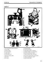
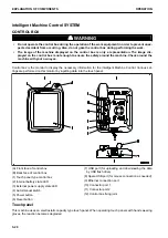
Control box is the monitor to display the necessary information for the intelligent Machine Control. Various set-
tings are performed on this monitor by inputting data into the touch panel.
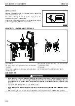
(A) Front face of control box
(B) Back face of control box
(1) Touch panel type control box
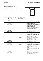
(2) Internal battery state LED
(3) External power supply state LED
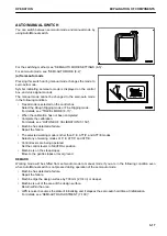
(4) Auto/manual switch
(5) Power button
(6) Reset button
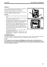
(7) USB port (for uploading and downloading the data
by USB flash drive)
(8) Spare USB port (for mouse connection as needed)
(9) Ethernet connection port
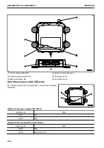
(10) Connector port 1
(11) Connector port 2
(12) Control box fixing joint
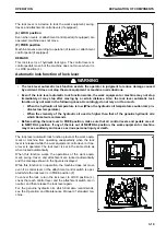
Touch panel
This machine uses an electrostatic capacity type touch panel. When operating touch panels with hands wearing
gloves, the reaction becomes degraded.
EXPLANATION OF COMPONENTS
OPERATION
3-20
Summary of Contents for A31001
Page 12: ...LOCATION OF SAFETY LABELS Options are shown with marks in the figure SAFETY LABELS SAFETY 2 4...
Page 106: ......
Page 107: ...SPECIFICATIONS 5 1...
Page 110: ......
Page 116: ......
Page 117: ...SETTING 7 1...
Page 311: ...EXECUTIONS 8 1...
Page 376: ...PC360LCi 11 PC390LCi 11 HYDRAULIC EXCAVATOR Form No CEAM032703...


