METHOD FOR ADJUSTING
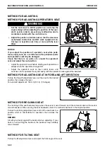
METHOD FOR ADJUSTING OPERATOR'S SEAT
k
k
WARNING
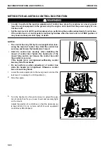
• Set the lock lever to LOCK position (L) and stop the
engine always when adjusting the position of the oper-
ator's seat in order to prevent any malfunction due to
accidental contact with the control levers.
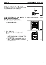
• Adjust the position of whole seat so that the clearance
(a) between control box and R.H. work equipment con-
trol lever is kept 40 mm {1.6 in} or more with the lever
tilted.
NOTICE
If you adjust the position of operator's seat while parts,
tools, empty cans, etc. are left around, the peripheral parts
and operator's seat may be damaged.
Check that there is no parts, etc. around the operator's
seat, and adjust the seat position.
• Adjust the operator's seat before starting each operation or
always when the operators change shift.
• Adjust the operator's seat so that control levers and
switches can be operated freely and easily with the operator's back against the backrest.
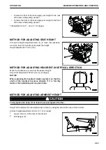
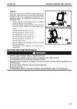
METHOD FOR ADJUSTING SEAT IN FORE-AND-AFT DIRECTION
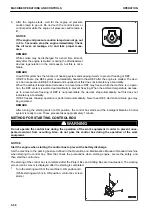
Pull up the fore-aft adjustment lever, set the seat to the desired
position, then release the lever.
Fore-and-aft adjustment: 160 mm {6.3 in} (16 stages)
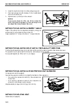
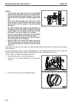
METHOD FOR RECLINING SEAT
The reclining of the seat becomes large when the seat is moved forward, and it becomes smaller as the seat is
moved backward. When moving the seat backward, return the reclined seat back to the original position.
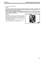
Pull up the reclining adjustment lever and set the seat back to a
position which is comfortable for operation, then release the
lever.
REMARK
Sit with your back against the backrest when adjusting. If your
back is not touching the backrest, the backrest may suddenly
move forward.
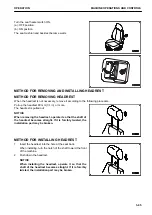
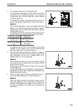
METHOD FOR TILTING SEAT
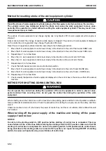
Pull up the tilt adjustment lever and adjust the front angle of the seat.
MACHINE OPERATIONS AND CONTROLS
OPERATION
3-42
Summary of Contents for A31001
Page 12: ...LOCATION OF SAFETY LABELS Options are shown with marks in the figure SAFETY LABELS SAFETY 2 4...
Page 106: ......
Page 107: ...SPECIFICATIONS 5 1...
Page 110: ......
Page 116: ......
Page 117: ...SETTING 7 1...
Page 311: ...EXECUTIONS 8 1...
Page 376: ...PC360LCi 11 PC390LCi 11 HYDRAULIC EXCAVATOR Form No CEAM032703...


