2
1: Pulse control mode ―-4‖ – enable the driver through external digital input ........ 63
2 Pulse control mode ―-4‖ – enable the driver automatically after driver power on 64
– Speed Mode ............................................................................. 66
– Speed Mode ................................................................................. 67
– Torque Mode ............................................................................ 68
– Torque Mode ................................................................................ 70
Summary of Contents for CD2S Series
Page 7: ...7...
Page 8: ...8 1 3 3 Power Brake and Encoder cable of Motors...
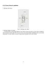
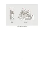
Page 12: ...12 Fig 2 3 Installation direction...
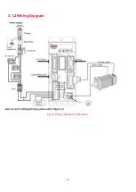
Page 15: ...15 3 1 2 Wiring Diagram Fig 3 1 Wiring diagram of CD2S driver...
Page 23: ...23 Fig 4 3 Separate regulation of bits...
Page 82: ...82...
Page 96: ...96 8 4 Debugging example 8 4 1 Oscilloscope 1 Enter oscilloscope 2 Parameters for Oscilloscope...
Page 98: ...98 In Auto Reverse mode Kvp 110...
Page 100: ...100 The oscilloscope is as following max following error is 69 inc Fig 2 Kpp 30 Vff 100...
Page 101: ...101 The oscilloscope is as following max following error is 53 inc Fig 3 Kpp 30 Vff 50...
Page 102: ...102 The oscilloscope is as following max following error is 230 inc...

