75
section 5 to 325)
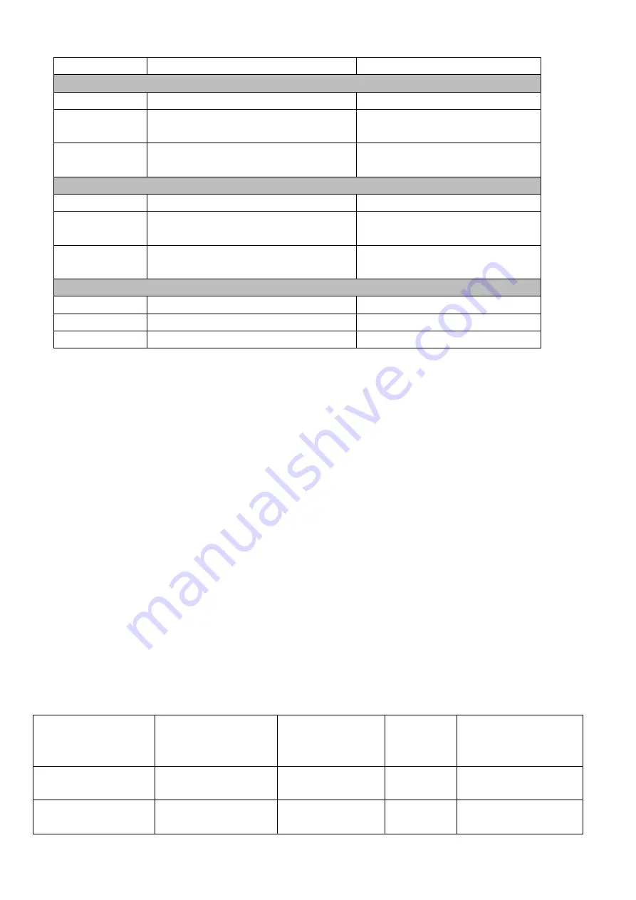
d3.41
Set position M
(
M*10000
)
Set to 0
d3.42
Set position N
Set to 850 (Set the position of
section 6 to 850)
d3.46
Set the speed of position section 6
Set to 275 (Set the speed of
section 6 to 275)
d3.41
Set position M
(
M*10000
)
Set to 1
d3.42
Set position N
Set to 5000 (Set the position of
section 7 to 15000)
d3.47
Set the speed of position section 7
Set to 460 (set the speed of
section 7 to 460)
d2.10
Acceleration
Default 610 rps/s
d2.11
Deceleration
Default 610 rps/s
d3.00
Save control loop parameters
Set to 1
Set all these parameters, then
:
1. Enable the driver, which means to make the digital input DIN1 high-level.
2. Select the position section, which means to change the electrical level of DIN4,DIN5 and DIN6.
3. Activate instructions and execute the program, which means to make the digital input DIN7 high-level.
Notice:
In
Multi-position
control mode, select location method by setting the different value of the digital tube d3.43.If
you choose
absolute positioning mode, set it to ―F‖; if the instructions require immediate updating, set it
to ―2F‖; if you choose relative positioning method, set it to ―4F‖.To change these parameters successfully,
you have to save the value of d3.00,and then restart.
7.5 Internal Multi-
speed Control Modes (“-3” or “3” Mode)
In this control mode, external input signals are used to activate the internally configured target speed to
control the motor. There are two prerequisites for activation:
1. Multi-
speed control is available in the ―-3‖ or ―3‖ mode, and is unavailable in other modes.
2. Set d3.28 to 0. In this case, the analog
– speed channel is invalid.
3. At least one external input signal DinX_Function defines Bit8 or Bit9.
For example, define Din2_Function corresponding to Din2 as 010.0, and Din3_Function corresponding
to Din3 as 020.0. In this way, the combination of the two above signals is used to choose any one of
Din_Speed0_RPM, Din_Speed1_RPM, Din_Speed2_RPM or Din_Speed3_RPM as the target speed.
Table 7-24 Parameters for internal
Multi-speed
control modes
Internal
Speed
Control 0
(Din_Sys.Bit8)
Internal
Speed
Control 1
(Din_Sys.Bit9)
Meaning
Numeric
Display
Valid Object
(numeric
display
operation)
0
0
Multi-speed
control: 0 [rpm]
d3.18
Din_Speed0_RPM
1
0
Multi-speed control
1 [rpm]
d3.19
Din_Speed1_RPM
Summary of Contents for CD2S Series
Page 7: ...7...
Page 8: ...8 1 3 3 Power Brake and Encoder cable of Motors...
Page 12: ...12 Fig 2 3 Installation direction...
Page 15: ...15 3 1 2 Wiring Diagram Fig 3 1 Wiring diagram of CD2S driver...
Page 23: ...23 Fig 4 3 Separate regulation of bits...
Page 82: ...82...
Page 96: ...96 8 4 Debugging example 8 4 1 Oscilloscope 1 Enter oscilloscope 2 Parameters for Oscilloscope...
Page 98: ...98 In Auto Reverse mode Kvp 110...
Page 100: ...100 The oscilloscope is as following max following error is 69 inc Fig 2 Kpp 30 Vff 100...
Page 101: ...101 The oscilloscope is as following max following error is 53 inc Fig 3 Kpp 30 Vff 50...
Page 102: ...102 The oscilloscope is as following max following error is 230 inc...


