77
d3.02
Din2_Function
Set to 000.4
(control over operation modes of drivers)
d3.06
Din6_Function
Set to 010.0
(internal speed control 0)
d3.07
Din7_Function
Set to 020.0
(internal speed control 1)
d3.16
Din_Mode0
Set to 0.003 (3) mode
(speed mode with acceleration/deceleration)
d3.17
Din_Mode1
Set to 0.003 (-3) mode
(instantaneous speed mode)
d3.18
Din_Speed0_RPM
Set to 100 [rpm]
d3.19
Din_Speed1_RPM
Set to 200 [rpm]
d3.20
Din_Speed2_RPM
Set to 300 [rpm]
d3.21
Din_Speed3_RPM
Set to 400 [rpm]
d3.00
Store_Loop_Data
Set to 1
7.7 Homing Mode (“6” Mode)
1, Summary
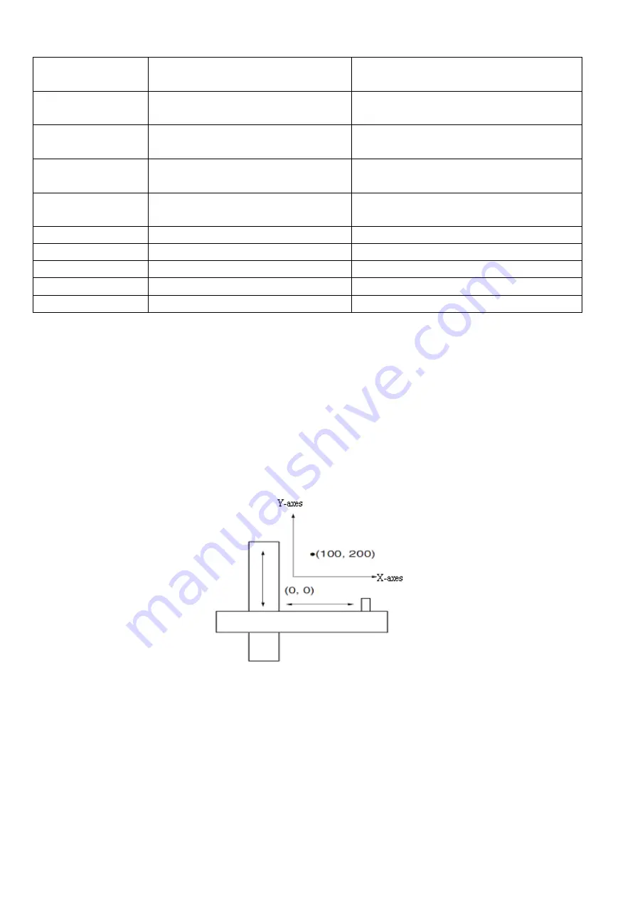
To make a system execute positioning in accordance with its absolute positioning, the first step is to define
the origin. For instance, as shown in the following XY plane, to navigate to (X, Y) = (100mm, 200mm), you
must define the origin of the machine firstly. It’s necessary to define the origin.
2, Procedure of homing
Use the following steps to homing:
1. Set the external I / O parameters, and then save.
2. Set the data for homing, and then save.
3. Execute homing.
3, Configuration of the data for homing
Here are simple descriptions of the data for executing homing.
Summary of Contents for CD2S Series
Page 7: ...7...
Page 8: ...8 1 3 3 Power Brake and Encoder cable of Motors...
Page 12: ...12 Fig 2 3 Installation direction...
Page 15: ...15 3 1 2 Wiring Diagram Fig 3 1 Wiring diagram of CD2S driver...
Page 23: ...23 Fig 4 3 Separate regulation of bits...
Page 82: ...82...
Page 96: ...96 8 4 Debugging example 8 4 1 Oscilloscope 1 Enter oscilloscope 2 Parameters for Oscilloscope...
Page 98: ...98 In Auto Reverse mode Kvp 110...
Page 100: ...100 The oscilloscope is as following max following error is 69 inc Fig 2 Kpp 30 Vff 100...
Page 101: ...101 The oscilloscope is as following max following error is 53 inc Fig 3 Kpp 30 Vff 50...
Page 102: ...102 The oscilloscope is as following max following error is 230 inc...


