55
unchanged in the window (d3.39) of the time of reaching the
target position, and position errors are within the window of
reaching the target position.
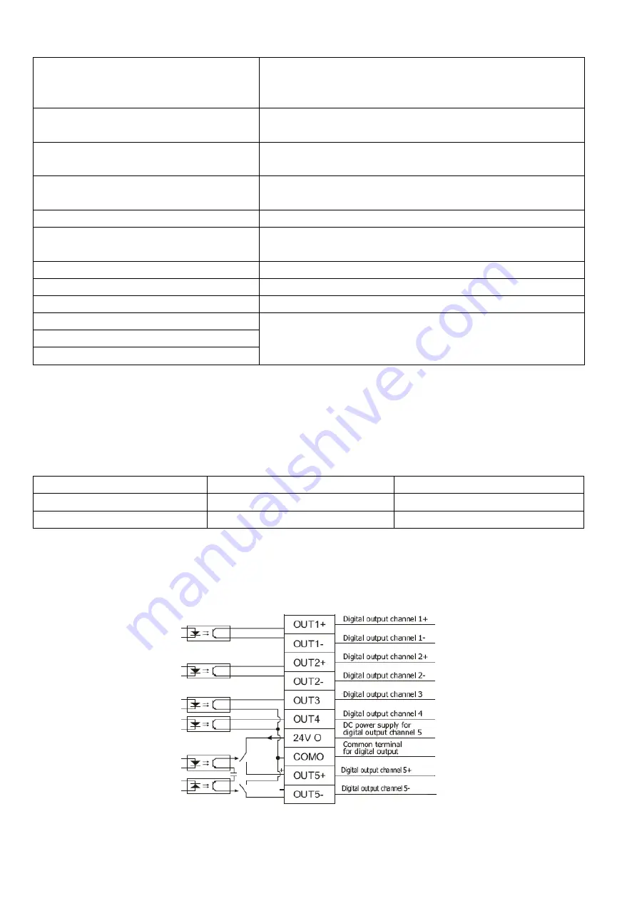
Zero velocity
After the motor is enabled, it is outputted when the motor speed
is 0.
Motor brake
The driver enables the motor, and contracting brake output is
valid.
Velocity reached
In the ―-3‖ or "3‖ internal speed control mode, signals are output
after they reach the target speed.
Index
Z phase signal output (the speed should not be too high).
Max. velocity limit
In the ―4‖ analog – torque mode, signals are output after the
max restricted speed is reached.
PWM ON
The driver enables the motor.
Motor limiting
Motor is in the status of position limiting.
Reference found
Homing is finished.
Multi Dout 0
Position reach for internal multiple position mode.
Multi Dout 1
Multi Dout 2
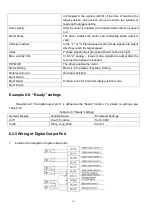
Example 6-
6: “Ready” settings
Requirement: The digital output port 1 is defined as the ―Ready‖ function. For details on settings, see
Table 6-19.
Table 6-
19: ―Ready‖ settings
Numeric Display
Variable Name
Parameter Settings
d3.11
Dout1_Function
Set to 000.1
d3.00
Store_Loop_Data
Set to 1
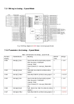
6.2.5 Wiring of Digital Output Port
1. Internal circuit diagram of digital output ports
Summary of Contents for CD2S Series
Page 7: ...7...
Page 8: ...8 1 3 3 Power Brake and Encoder cable of Motors...
Page 12: ...12 Fig 2 3 Installation direction...
Page 15: ...15 3 1 2 Wiring Diagram Fig 3 1 Wiring diagram of CD2S driver...
Page 23: ...23 Fig 4 3 Separate regulation of bits...
Page 82: ...82...
Page 96: ...96 8 4 Debugging example 8 4 1 Oscilloscope 1 Enter oscilloscope 2 Parameters for Oscilloscope...
Page 98: ...98 In Auto Reverse mode Kvp 110...
Page 100: ...100 The oscilloscope is as following max following error is 69 inc Fig 2 Kpp 30 Vff 100...
Page 101: ...101 The oscilloscope is as following max following error is 53 inc Fig 3 Kpp 30 Vff 50...
Page 102: ...102 The oscilloscope is as following max following error is 230 inc...


