52
Display
d3.05
Din5_Function
Change the default value 001.0 (position positive limit) to 000.0
d3.06
Din6_Function
Change the default value 002.0 (position negative limit) to
000.0
d3.00
Store_Loop_Data
Set to 1
Example 6-5: Operation Mode Control on Drivers
Requirements: Defines the input port DIN3 as the operation mode control on drivers, and the operation
mode is ―-4‖ (pulse control mode) when DIN3 fails, and is ―-3‖ (instantaneous speed mode) when DIN3 is
valid. Table 6-13 describes the setup method.
Table 6-13 Settings on operation mode control on drivers
Numeric Display
Variable Name
Parameter Settings
d3.03
Din3_Function
Set to 000.4
d3.16
Din_Mode0
Set to 0.004 (-4)
d3.17
Din_Mode1
Set to 0.003 (-3)
d3.00
Store_Loop_Data
Set to 1
Note
: If the driver is required to operate in some mode with power on, one of the digital input must be set as
function ―Operation Mode Control‖. Then you can set the operation modes that require in the parameters
d3.16 or d3.37 in Group F003.
6.1.6
Wiring
of Digital Input Port
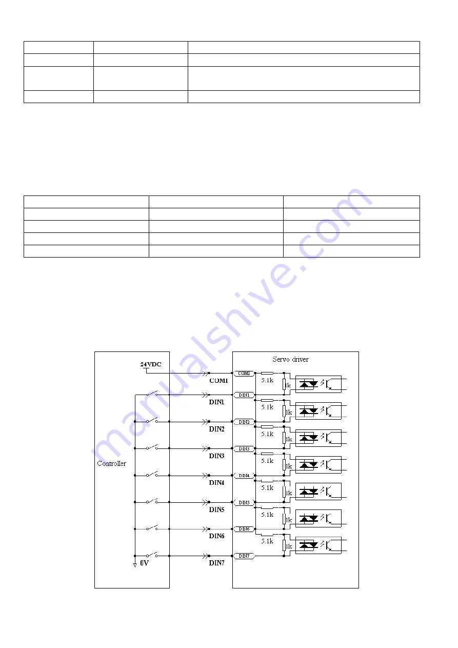
1. NPN wiring diagram (to the controller that supports low level output)
Fig. 6-2 NPN wiring diagram (to the controller that supports low level output)
Summary of Contents for CD2S Series
Page 7: ...7...
Page 8: ...8 1 3 3 Power Brake and Encoder cable of Motors...
Page 12: ...12 Fig 2 3 Installation direction...
Page 15: ...15 3 1 2 Wiring Diagram Fig 3 1 Wiring diagram of CD2S driver...
Page 23: ...23 Fig 4 3 Separate regulation of bits...
Page 82: ...82...
Page 96: ...96 8 4 Debugging example 8 4 1 Oscilloscope 1 Enter oscilloscope 2 Parameters for Oscilloscope...
Page 98: ...98 In Auto Reverse mode Kvp 110...
Page 100: ...100 The oscilloscope is as following max following error is 69 inc Fig 2 Kpp 30 Vff 100...
Page 101: ...101 The oscilloscope is as following max following error is 53 inc Fig 3 Kpp 30 Vff 50...
Page 102: ...102 The oscilloscope is as following max following error is 230 inc...


