21
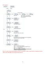
4.2 Operation on Digital Operation Panel
Power ON
Press
MODE
Switching of basic menus
Parameter display (current speed is
displayed by default)
Press
Press
Press
Press
Press
Press
Press
Press
Press
Press
Press
Press
Press
Press
Press
Press
Press
Set driver instructions
Set real-time display of data
Set control loop parameters
Settings
I/O parameters
Mode operation parameters
Set motor parameters
Set driver parameters
Trial operation
Check wrong history records
L
o
o
p
Fig. 4-1 Operation on a digital operation panel
Note:
If a non real-time display interface is displayed for the control panel, and no key operation occurs, the
real-time display interface is automatically skipped after 20 seconds to avoid misoperation.
Example 4-1: Set the denominator of electronic gear ratio to 10000 with
number system switching
1.
Press
MODE
. The main menu is displayed. Choose
F003
.
Summary of Contents for CD2S Series
Page 7: ...7...
Page 8: ...8 1 3 3 Power Brake and Encoder cable of Motors...
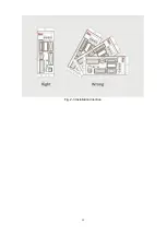
Page 12: ...12 Fig 2 3 Installation direction...
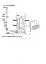
Page 15: ...15 3 1 2 Wiring Diagram Fig 3 1 Wiring diagram of CD2S driver...
Page 23: ...23 Fig 4 3 Separate regulation of bits...
Page 82: ...82...
Page 96: ...96 8 4 Debugging example 8 4 1 Oscilloscope 1 Enter oscilloscope 2 Parameters for Oscilloscope...
Page 98: ...98 In Auto Reverse mode Kvp 110...
Page 100: ...100 The oscilloscope is as following max following error is 69 inc Fig 2 Kpp 30 Vff 100...
Page 101: ...101 The oscilloscope is as following max following error is 53 inc Fig 3 Kpp 30 Vff 50...
Page 102: ...102 The oscilloscope is as following max following error is 230 inc...

